Noise Treatment
The difficult thing about addressing a problem that is loud and hot is that thermal insulating materials and acoustic insulating materials typically have completely different properties. Where thermal insulation is usually light and fluffy with a thin layer of Mylar or foil on one side, sound will travel right through that with no problem. On the other hand, dense materials that will cause sound to bounce off or reflect and otherwise interrupt the sound pressure waves is typically really good at transferring heat.
Everyone's situation will be different; my situation is that I share my home with my wife and our small children. In fact, my kids' room is directly above where the miner was installed so I had no choice but to address the problems of heat and noise. If you have family, roommates, or close neighbors and you want to mine at home, you too will need to be resourceful and creative when addressing these problems.
Industrial settings can make as much noise and heat as they want, they have a totally different set of problems than those of us mining at home. Industrial miners usually have huge warehouses with hundreds of thousands of cubic feet of air, massive ventilation fans, cheaper electricity, and they are typically set far apart from residential areas. Home mining on the other hand, will typically need to have the highest hashrate possible to run as efficiently as possible since residential electricity is so expensive. This means lots of noise and lots of heat. It's important to understand that once you start mining at home, you will not be able to shy away from these problems, your family, roommates, or neighbors will not let you. So be prepared to come up with solutions to these problems that suit your unique situation.
My basic idea was to build an enclosure that would mitigate the noise and allow sufficient air flow to keep the ASIC cool. I wanted to take careful considerations in building the enclosure so that I didn't inadvertently make the problems worse. Even though I have worked in the mechanical trades my entire adult life, my formal education is in audio. Because of that background I know that square spaces with parallel surfaces can create standing waves, which can actually amplify certain noises if the dimensions of the space align with the wavelengths of the noise. I wanted to be careful not to do that and some of the best noise treatment solutions to that problem are to make sure none of the surfaces are parallel and to make sure that none of the dimensions match the wavelengths of the noise being treated.
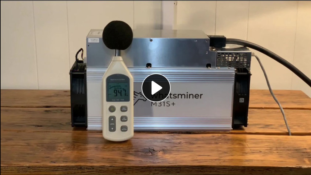
To better understand what I was working with, I made a 12 minute audio recording of the ASIC running to give me an idea of the machine's basic noise profile. When displayed on a spectrogram, time runs along the X-axis, frequency runs along the Y-axis, and the amplitude of the frequency over time is displayed as brighter in color for higher volumes. The 2-channel, stereo recording looked like this:
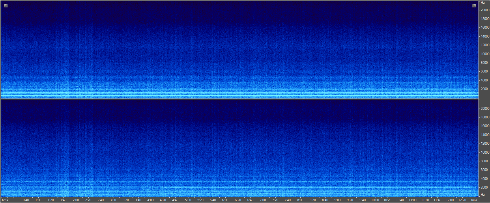
This provides some information but not a lot of detail. It can be deduced that there is a relatively even spread of noise at medium amplitude across a wide range of frequency with a few bands of high amplitude constant noise at some particular frequencies displayed near the bottom of the graph as bright horizontal lines. Contrary to popular belief due in part to the CSI-Effect, one cannot simply zoom and enhance there way to clearer details. Below is what the spectrogram looks like when one simply zooms in. We can see that the loudest noise is a horizontal band between 600Hz and 800Hz but in terms of wavelength, that's a range of ~17" to ~23" in dimensions that will be excluded from the design of my enclosure.
In order to gain more detail from this information it is necessary to apply some audio clarification techniques to enhance those details to get a more precise understanding of what the problem is.
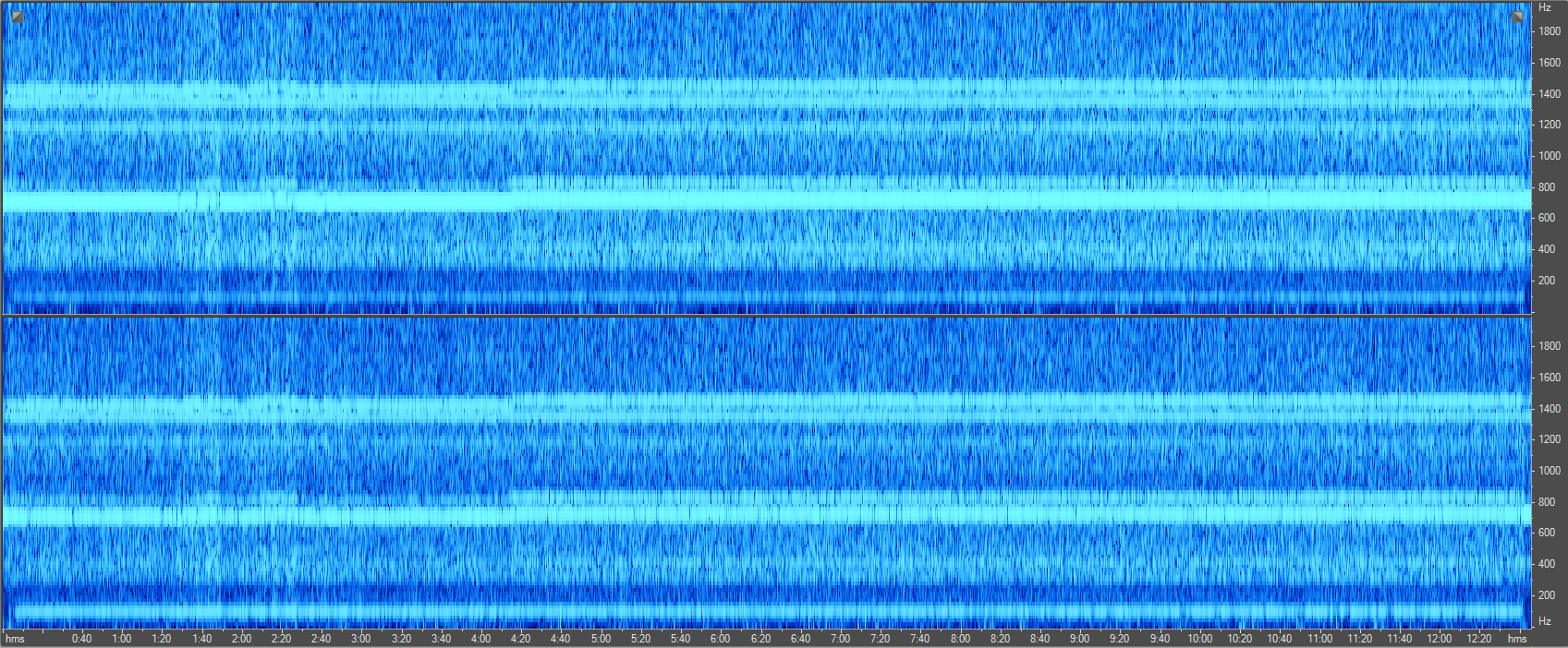
Since the lowest and brightest horizontal band is in between 600Hz and 800Hz and the other horizontal bands above it follow it's basic pattern, it is reasonable to deduce that we have a fundamental frequency with several harmonic frequencies appearing at higher ranges, this is a very common phenomenon with sound. This means that by addressing the root of the problem, the harmonic frequencies will naturally be mitigated as well. Thus I can ignore the higher frequency content by reducing recording's sample rate to only two times (Nyquist theorem) the fundamental frequency I'm interested in and apply a low-pass filter to get rid of frequencies above ~2kHz.
I know that only a few audio nerds reading this will follow that last part, but it basically means that the spectrogram now looks like this:
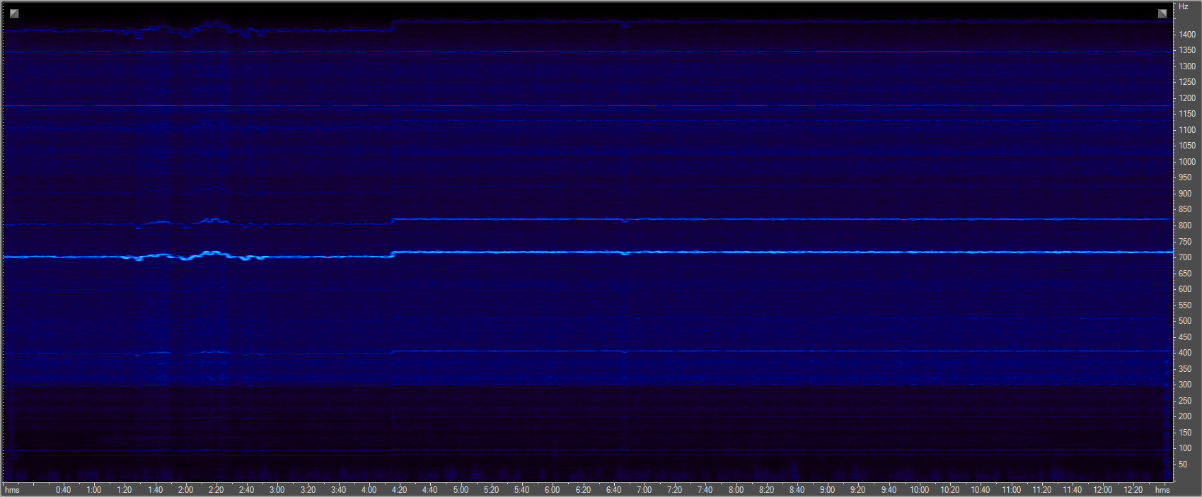
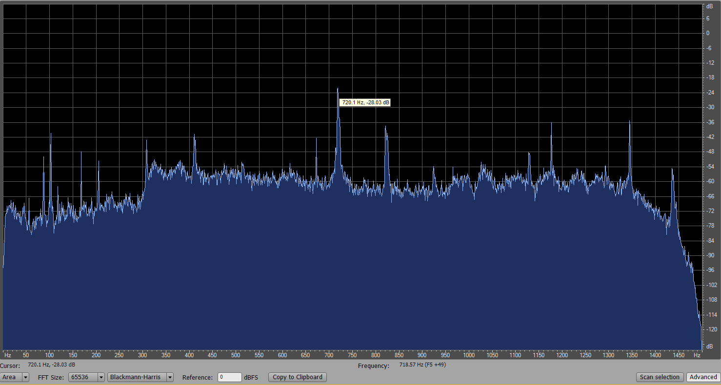
With a little more fine-tuning, one can zoom in and get the resulting precise frequency information needed to arrive at 720Hz. Which should have been obvious to me because it is a 12x multiple of 60Hz, the frequency at which power is being delivered to the ASIC.

720Hz is our culprit in this case, and that can also be confirmed by looking at the frequency on the X-axis and amplitude on the Y-axis.
Now the wave length of the problem frequencies can be calculated using the general variables of the properties of sound traveling at ~1,097 feet per second at ~72°F at an altitude of ~5,280 feet.
We get 1,097/720 = 1.52 feet or roughly 18-1/4". This means that any dimension in the enclosure that is 18.25", 9.125", 4.5625" or 36.5" will allow standing frequencies to occur that could actually amplify the 720 Hz noise. So I want to take these dimensions into careful consideration and avoid them when designing the enclosure.
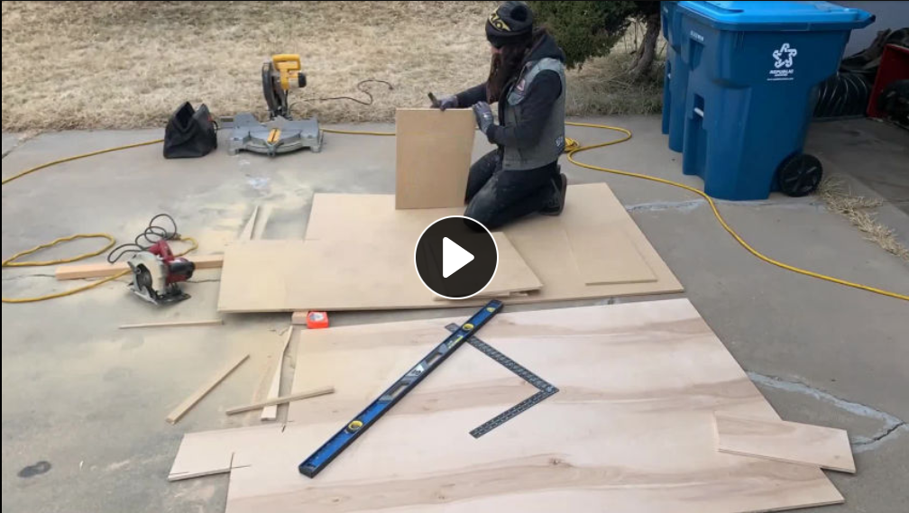
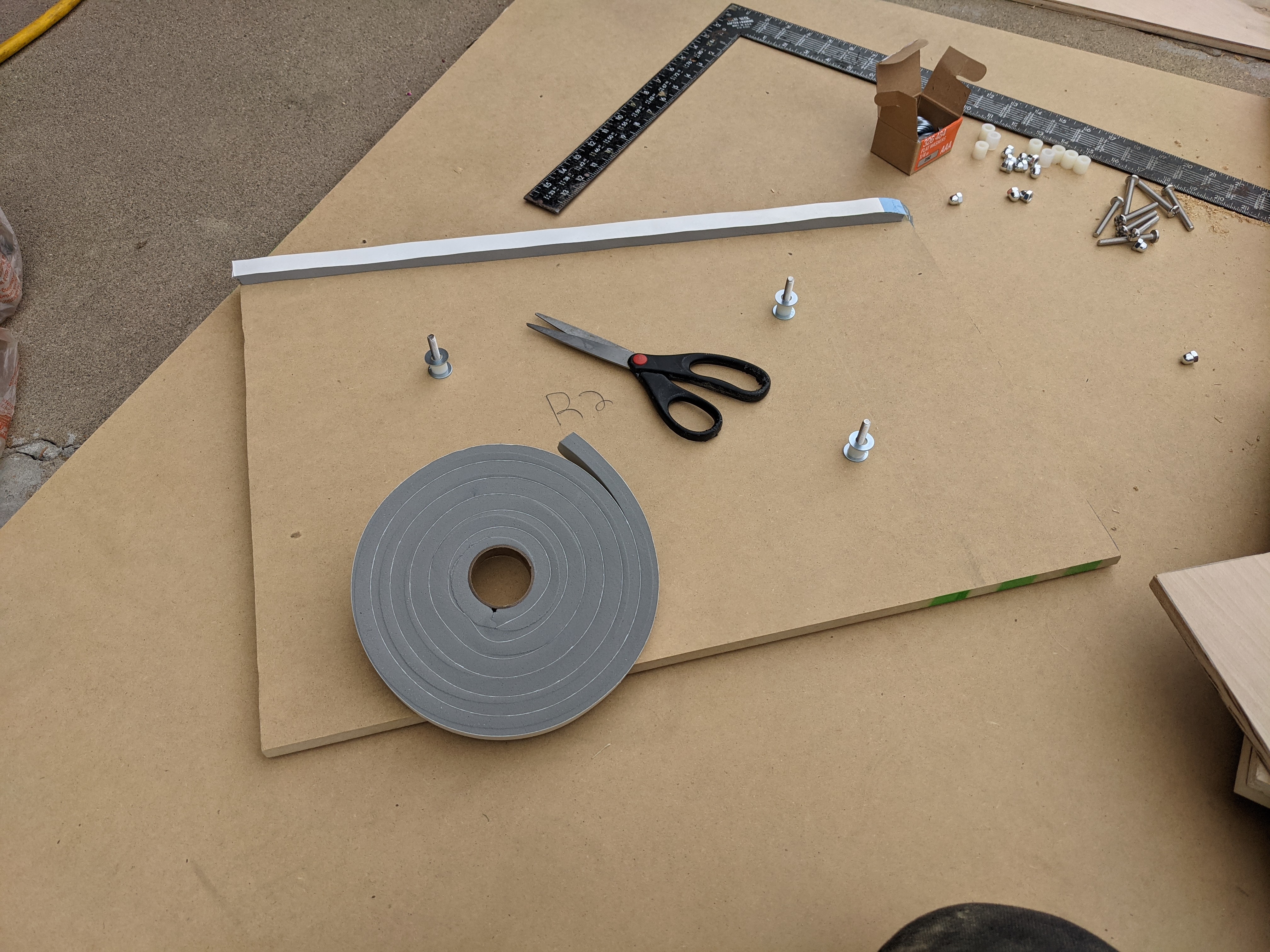
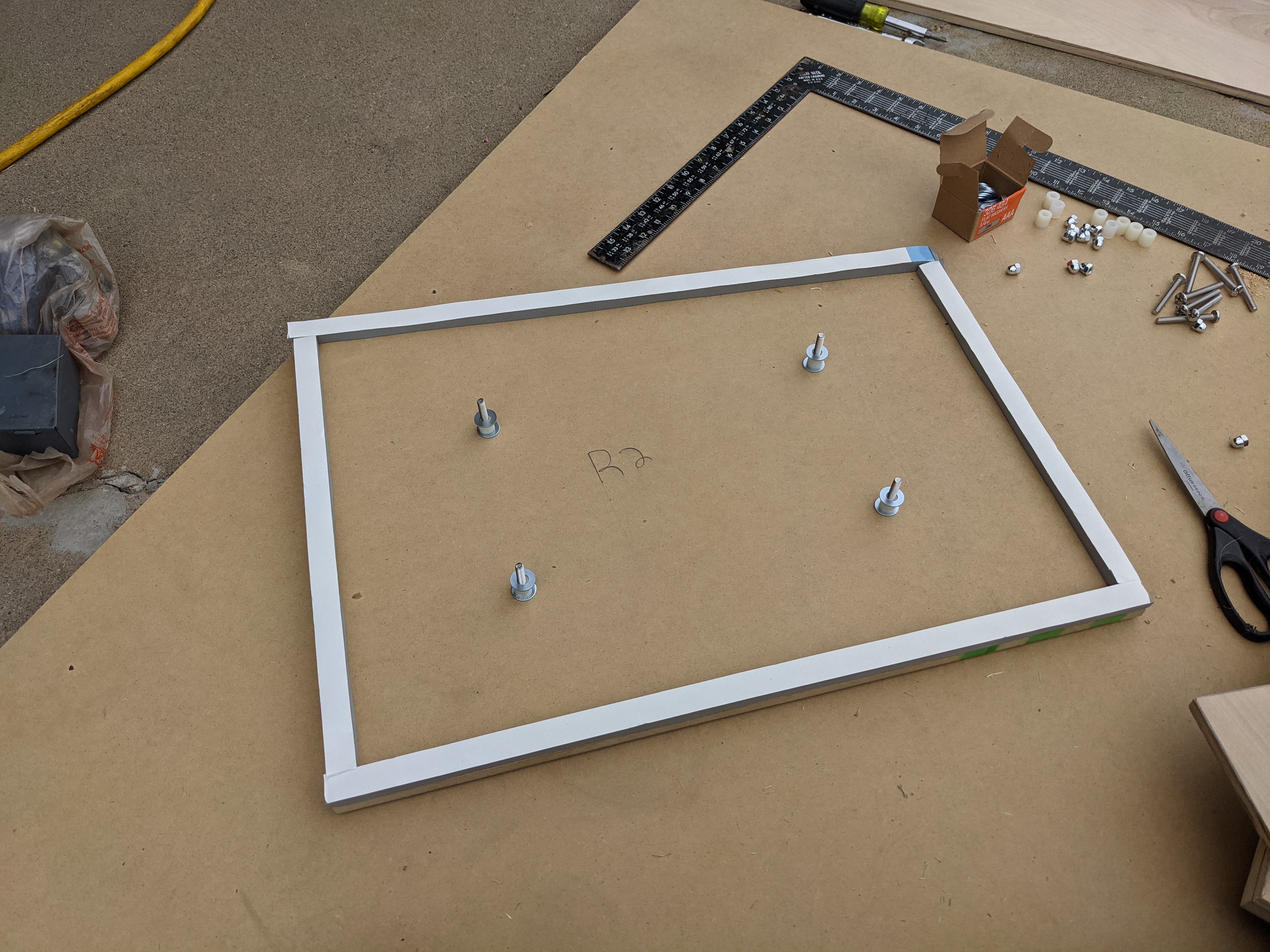
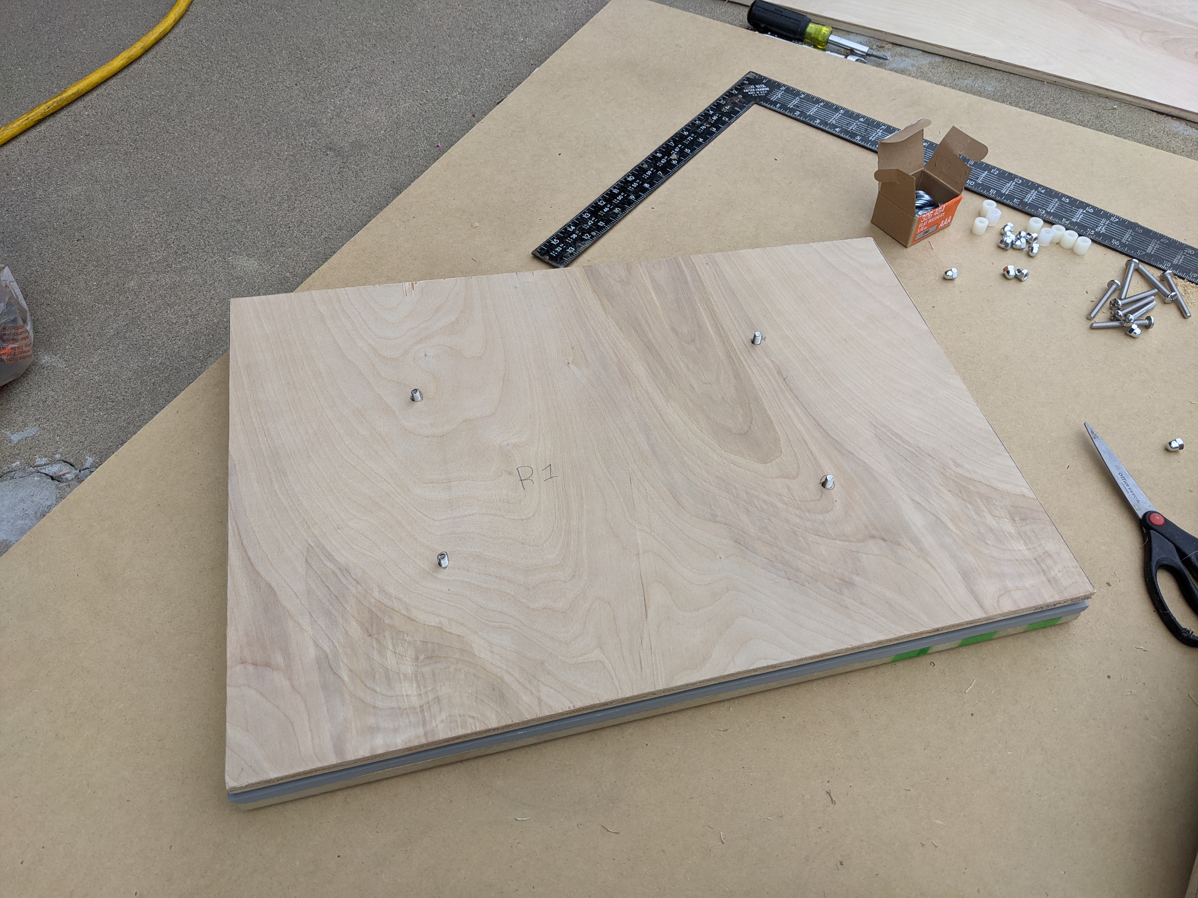
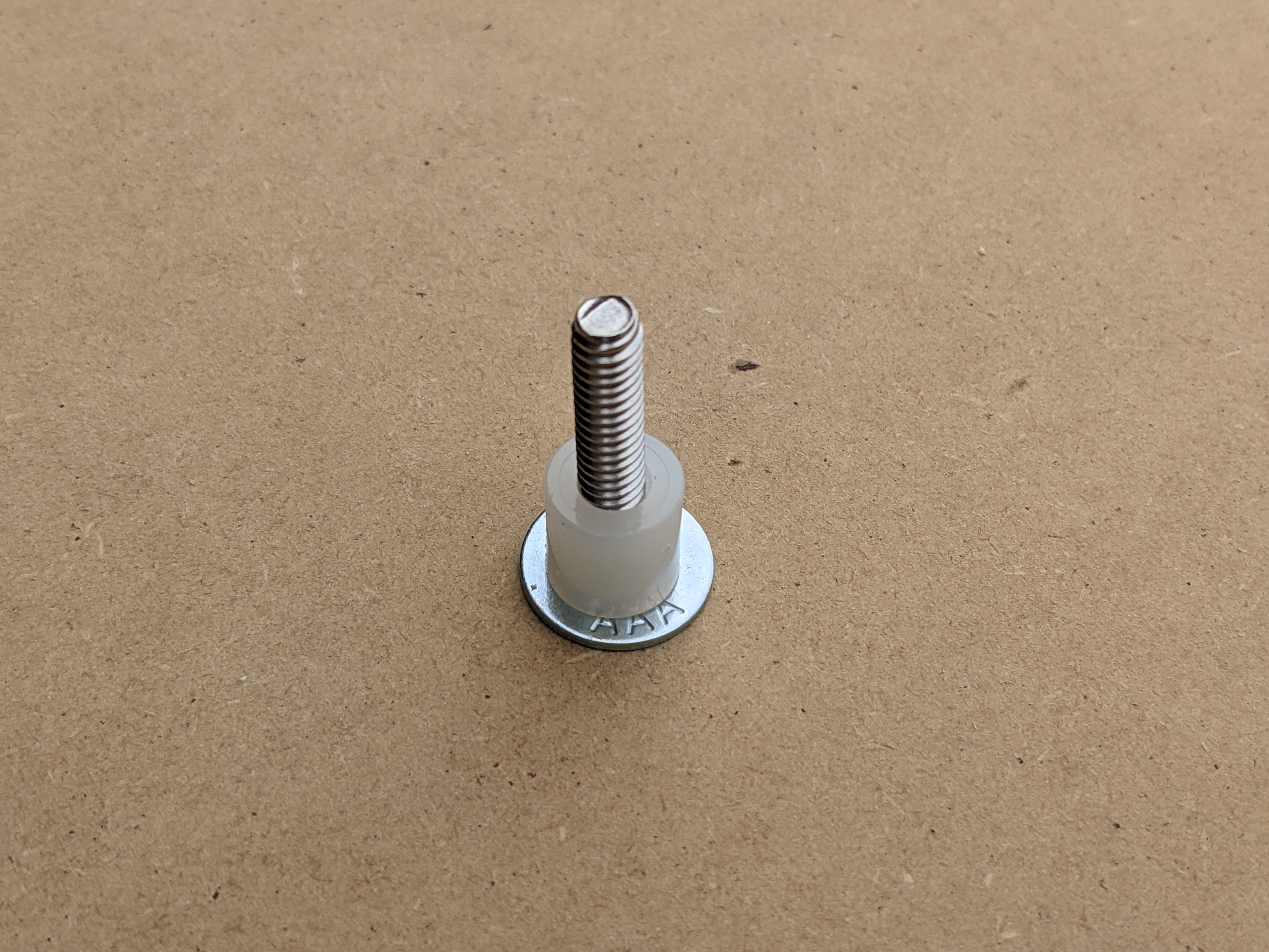
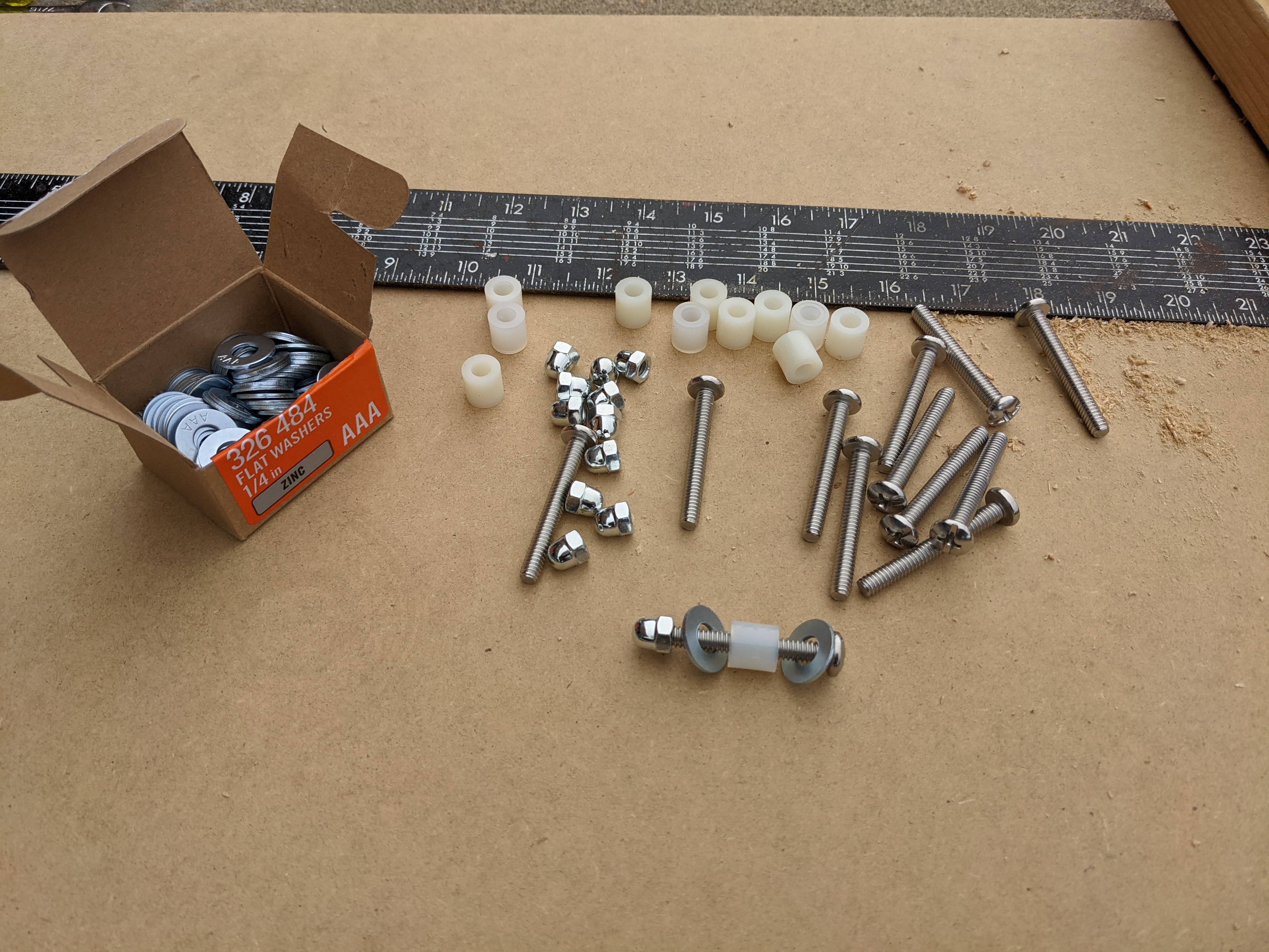
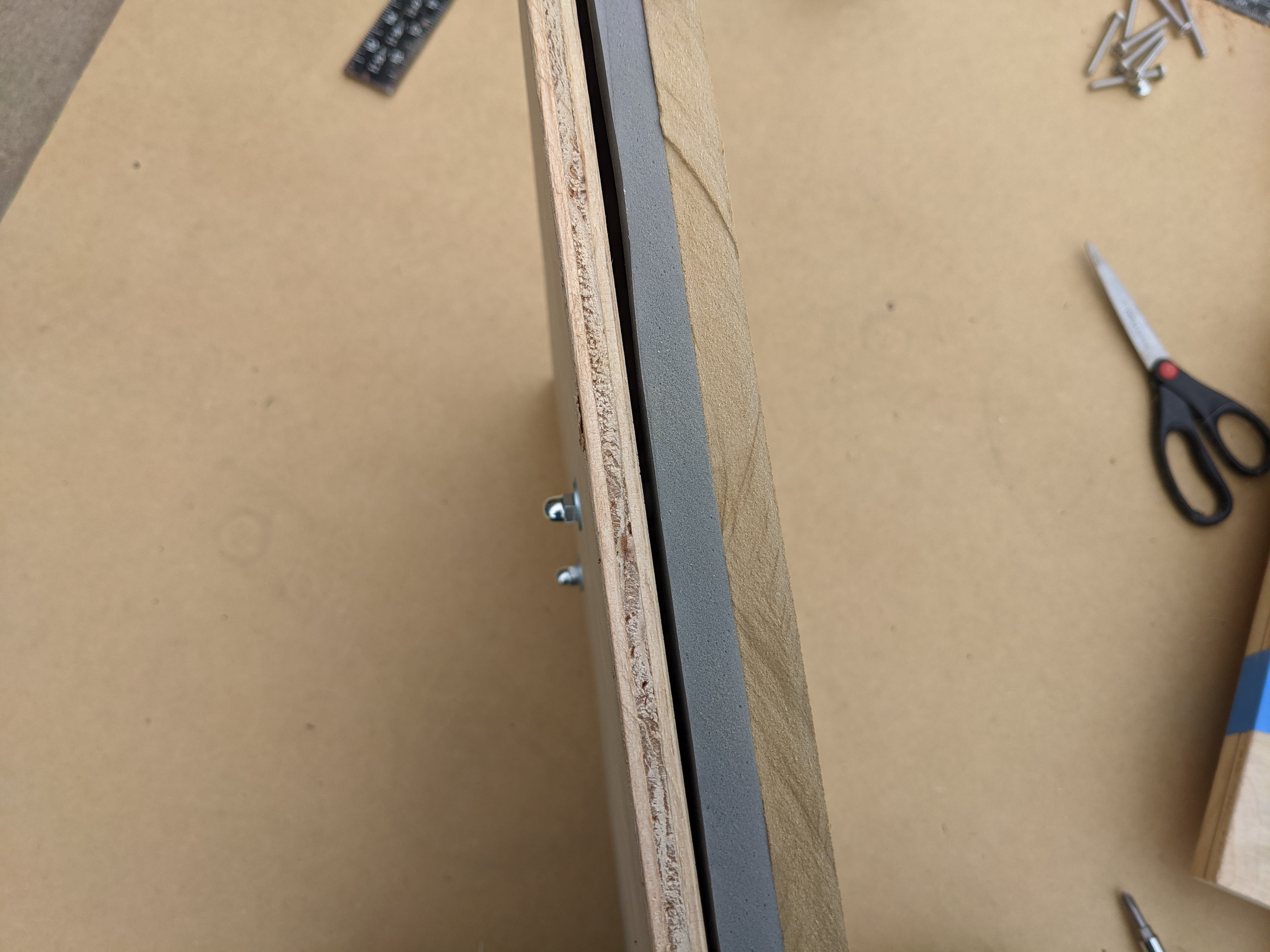
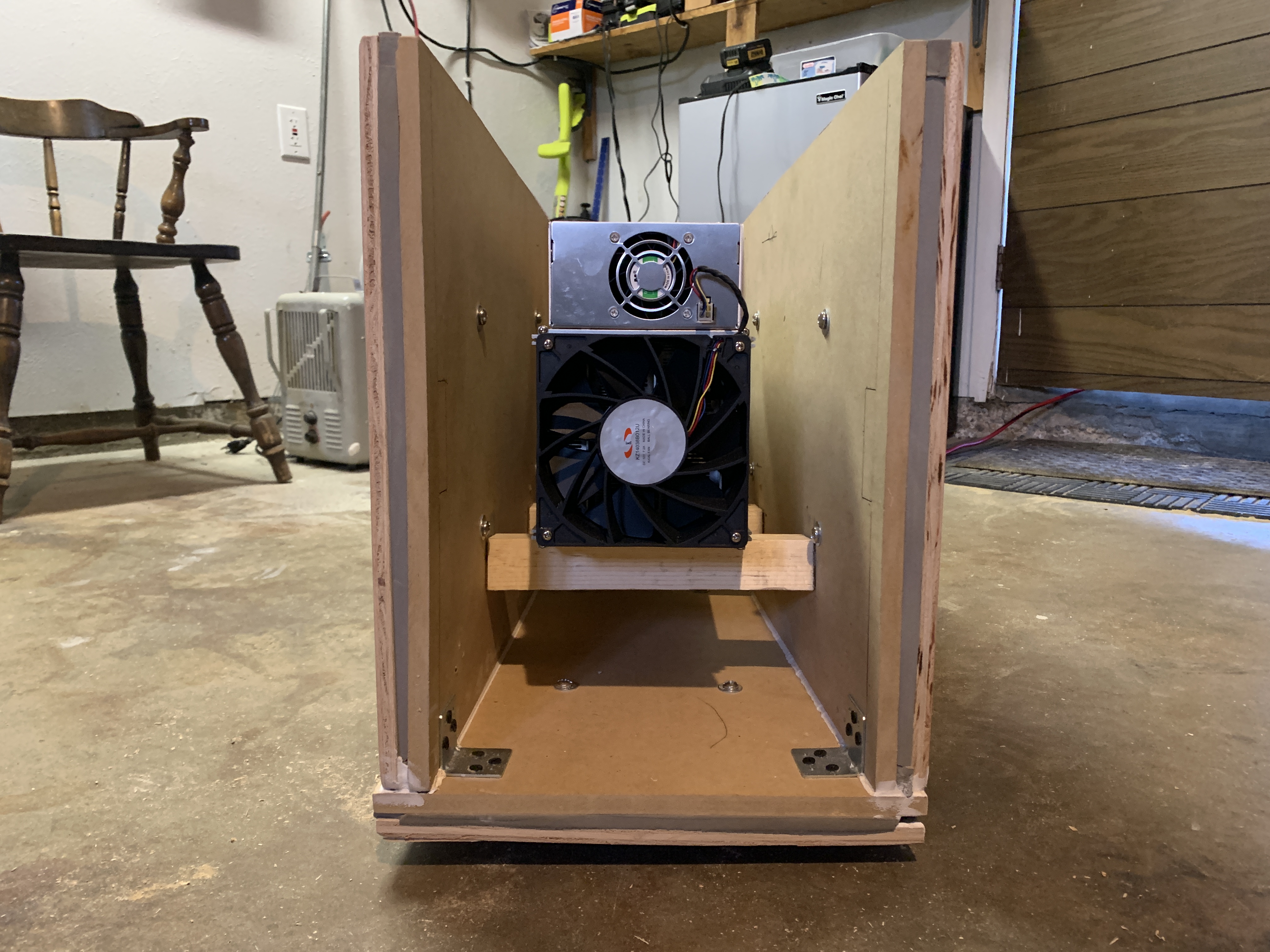
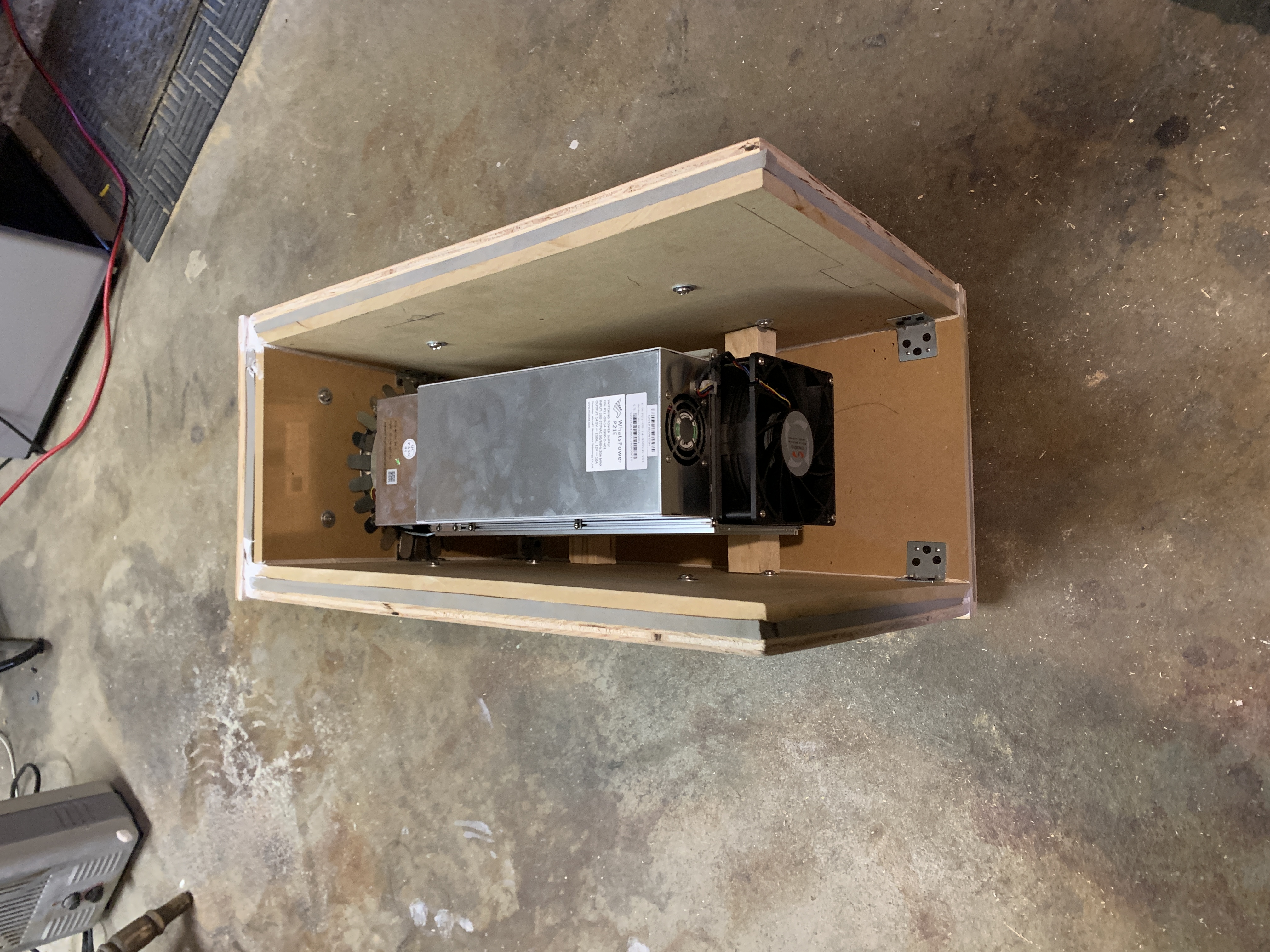
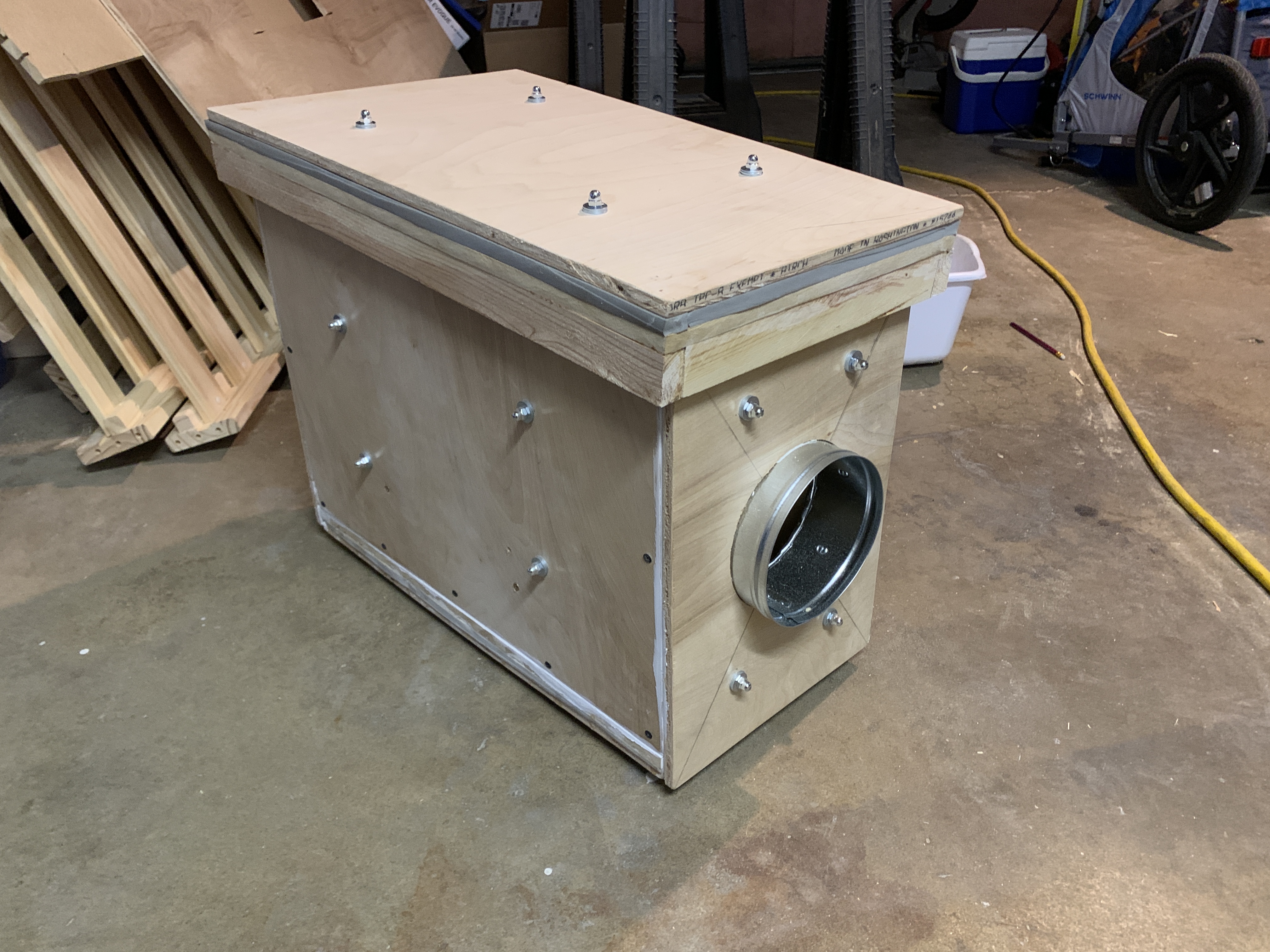
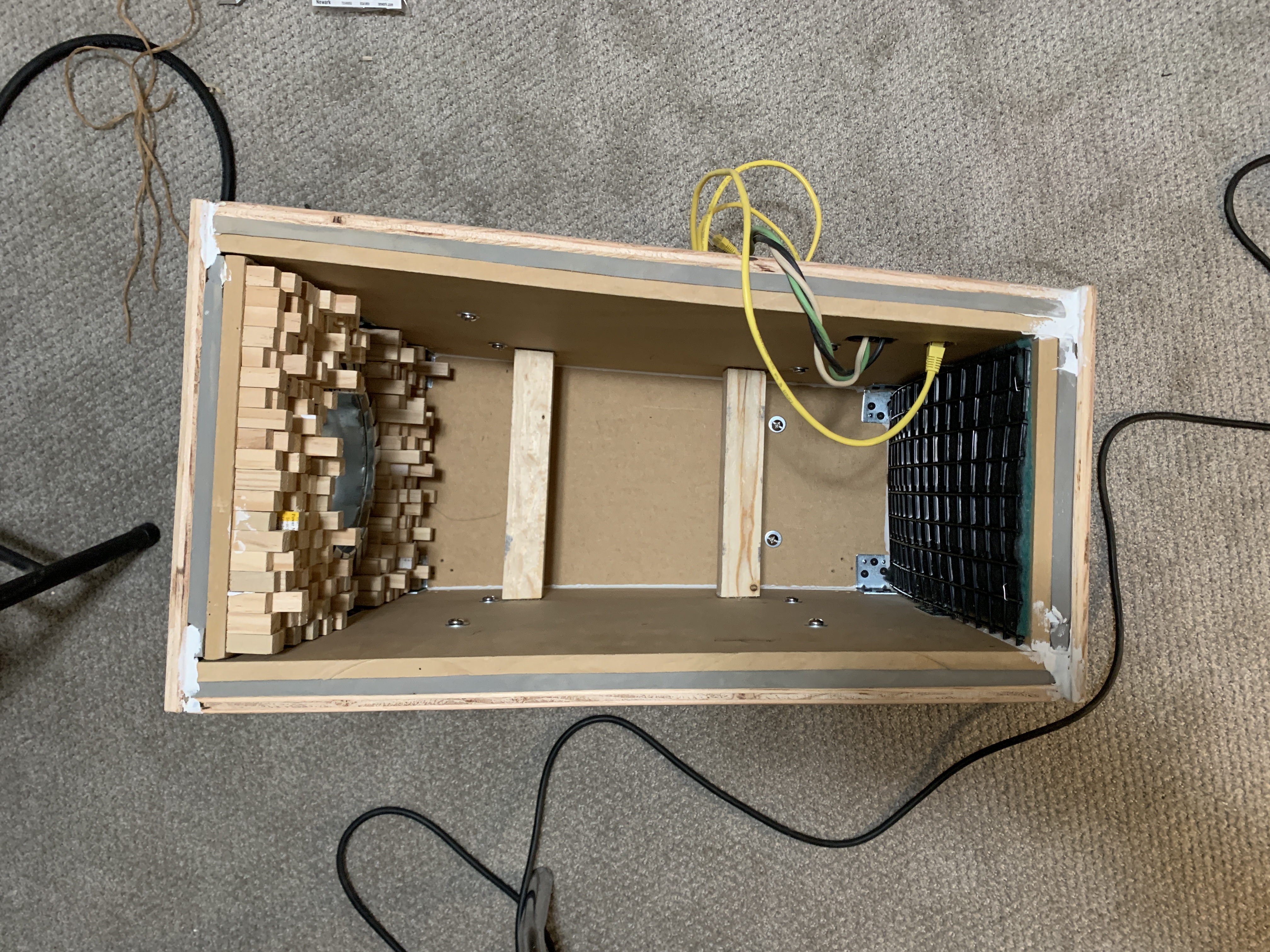
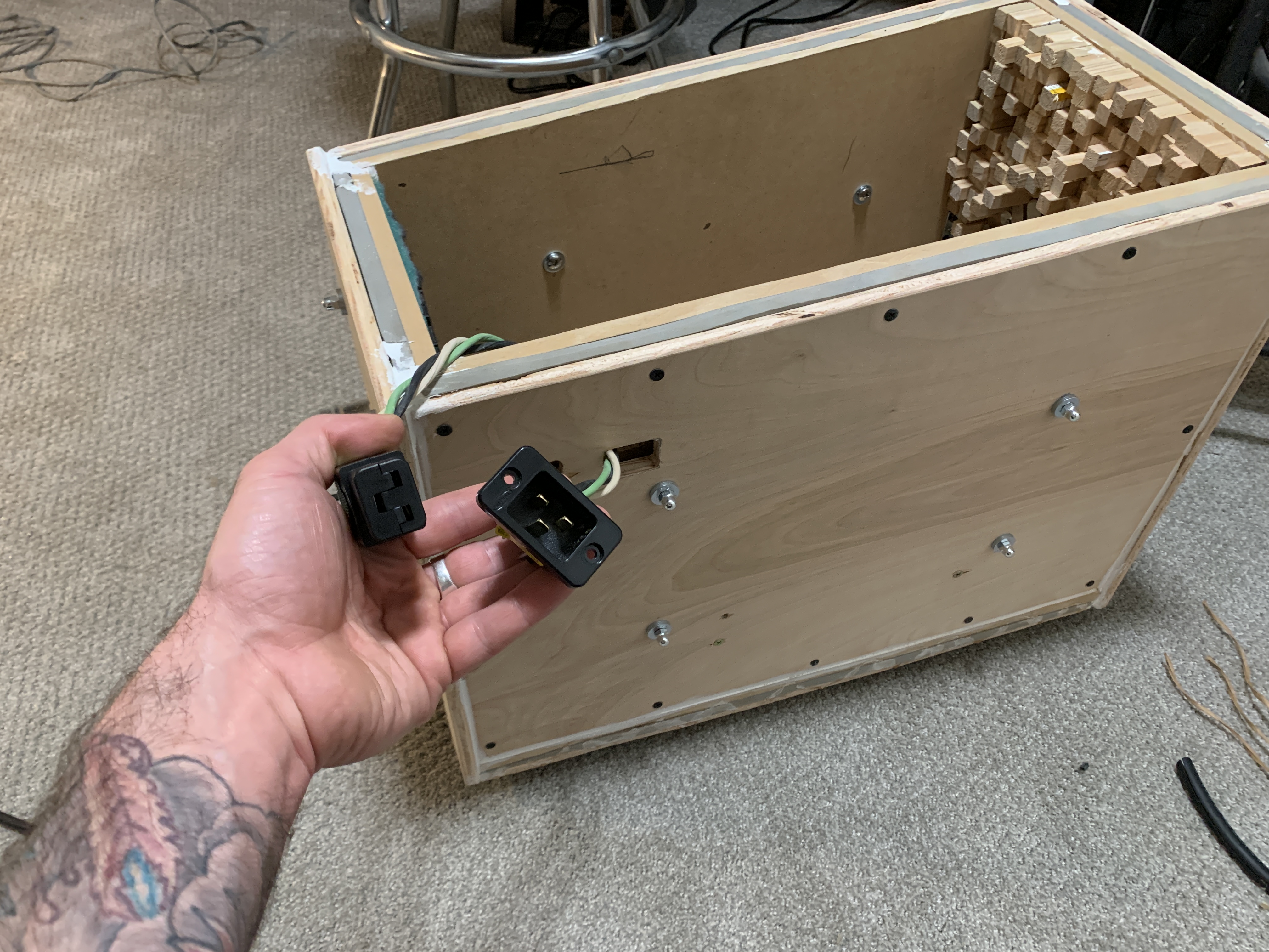
The next consideration that needs to be made is what materials to make the enclosure out of. Typically with noise treatment, the idea is to use different materials that will have different effects on the sound waves. I chose to use 1/2" Maximum Density Fiber (MDF) for the inside of the enclosure and 1/2" plywood for the outside of the enclosure. Then I separated the two layers with a 1/2" air gap. This way, the noise would have to travel through the MDF which based on it's density would effect the sound pressure waves in a certain way, then travel through a gap of dead air which would effect the sound pressure waves a different way, and finally through the plywood which would have yet another effect on the sound pressure waves.
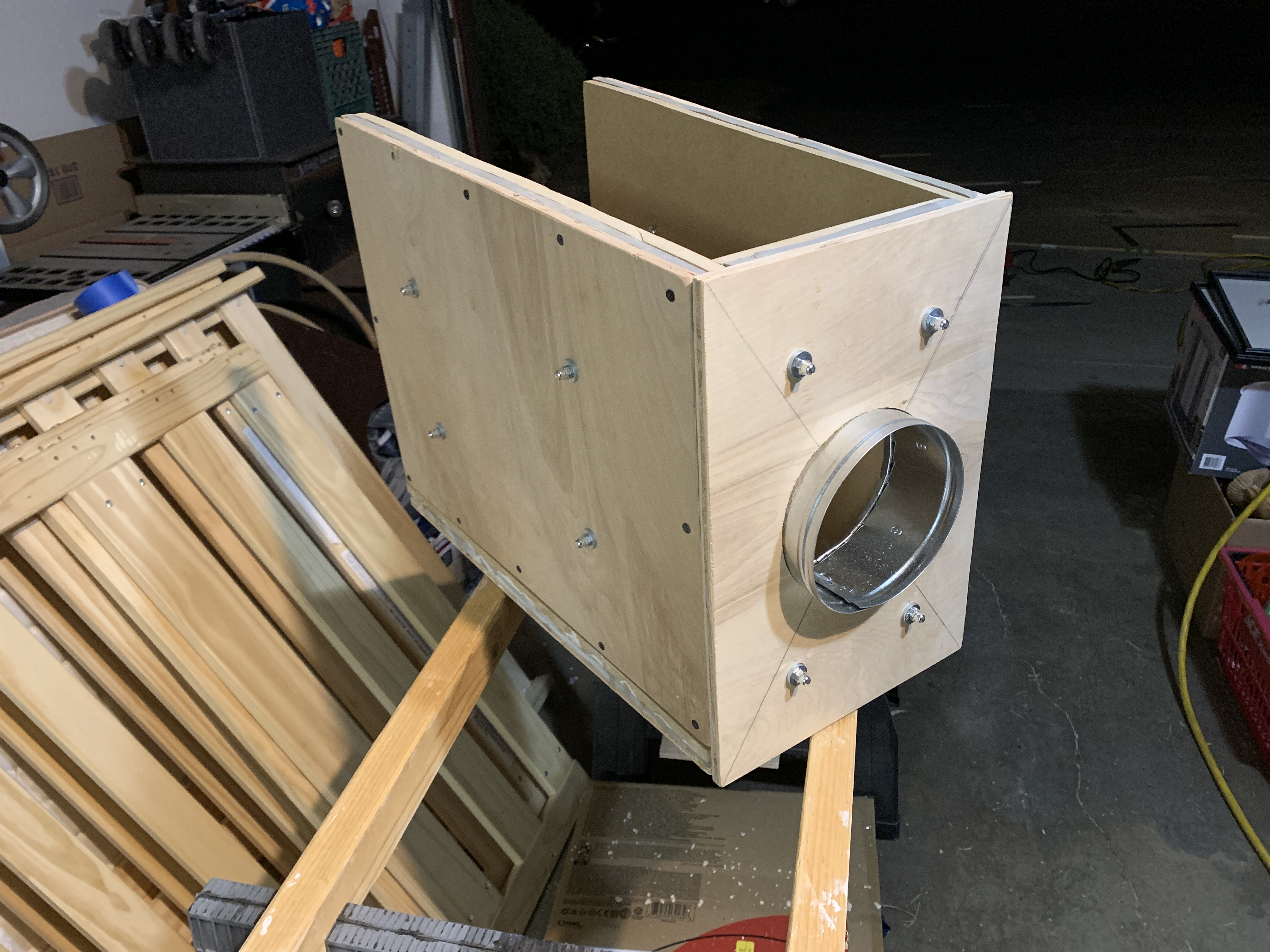
I purposely designed the enclosure so that it was out of square. Shorter and thinner on the input side; taller and wider on the output side. Keeping the surfaces un-parallel helps mitigate the possibility of standing waves.

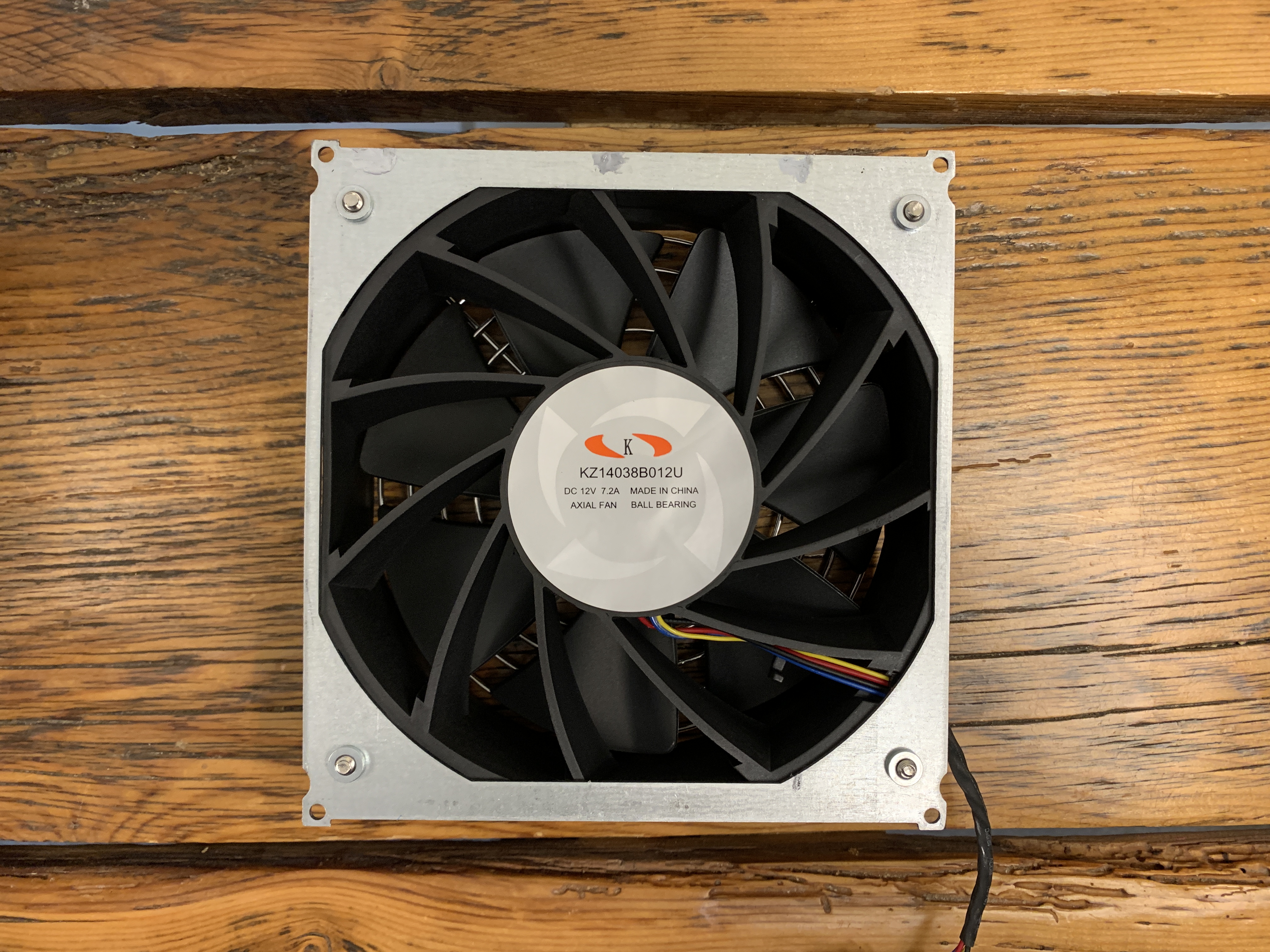
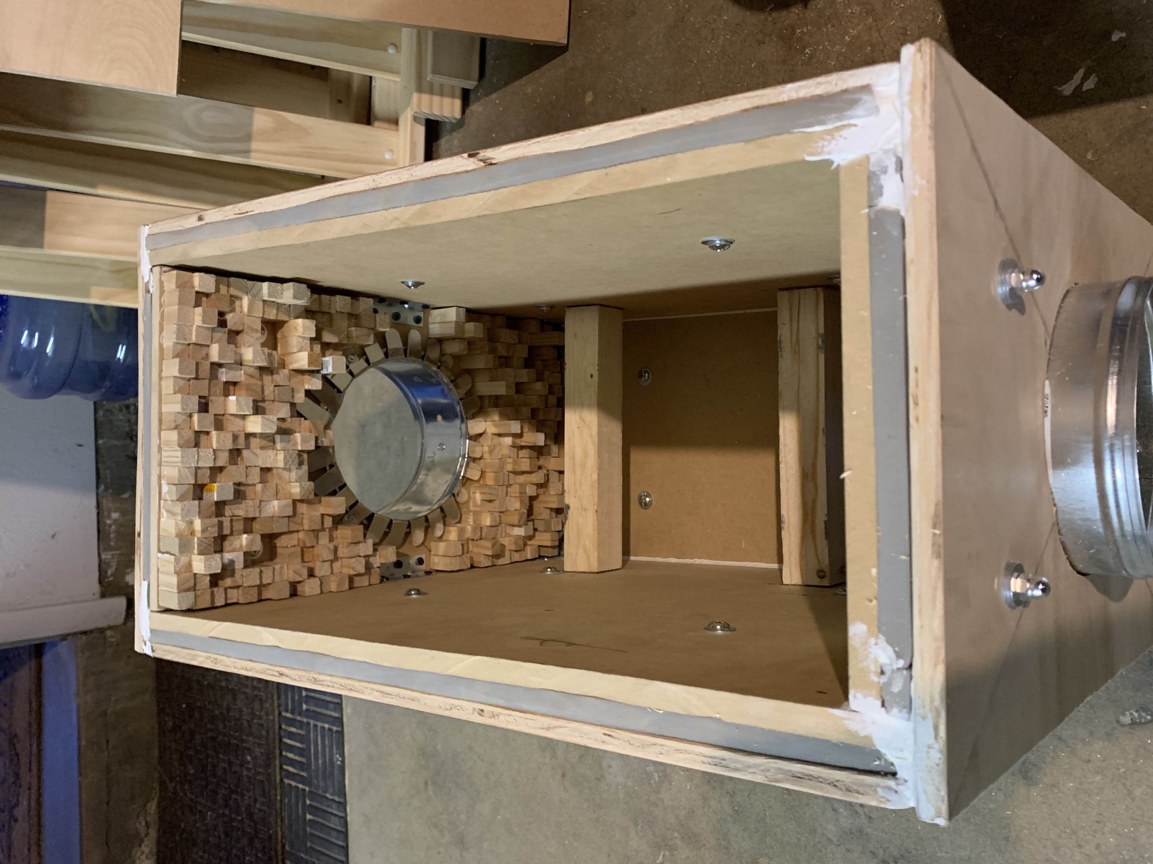
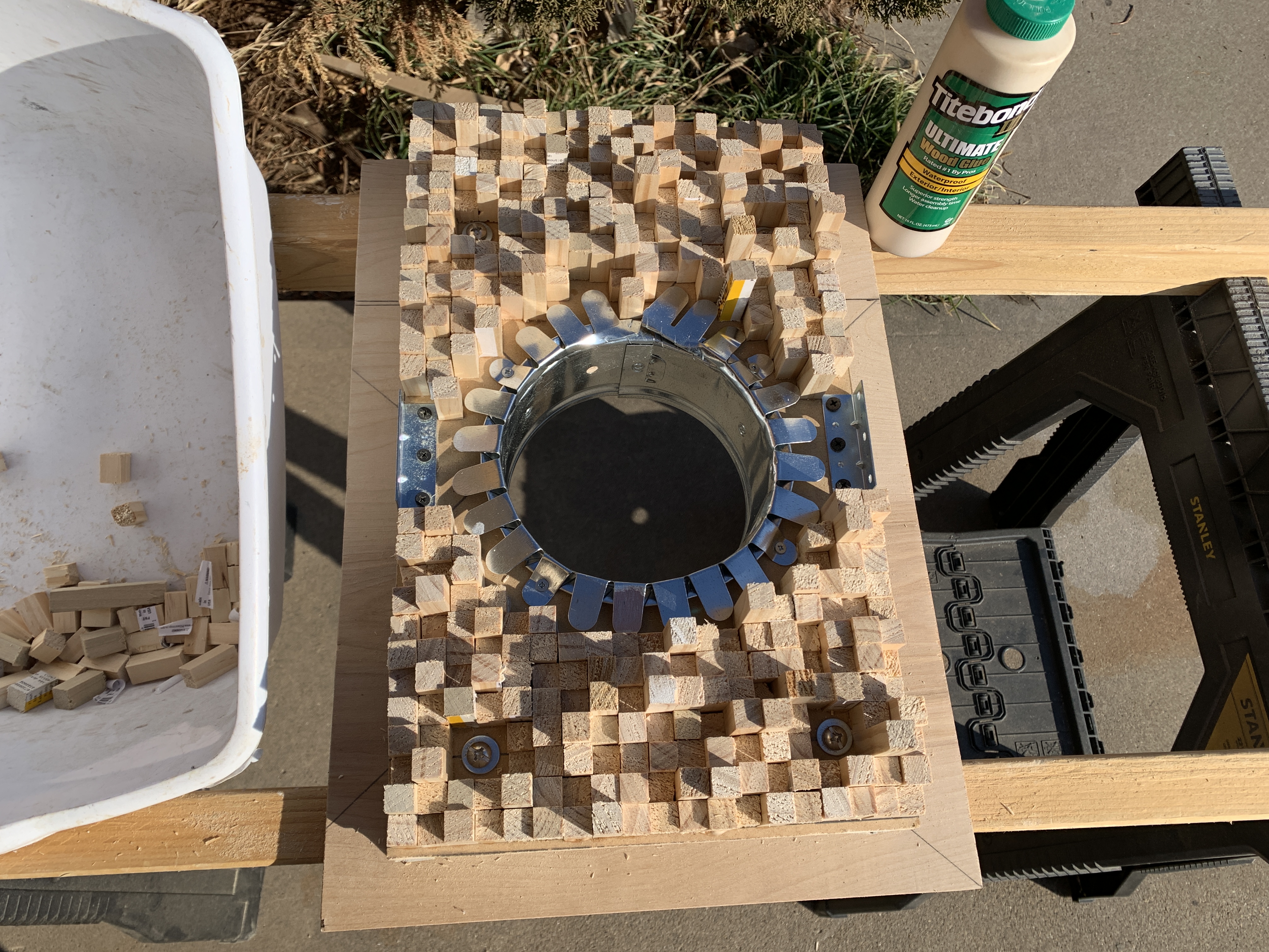
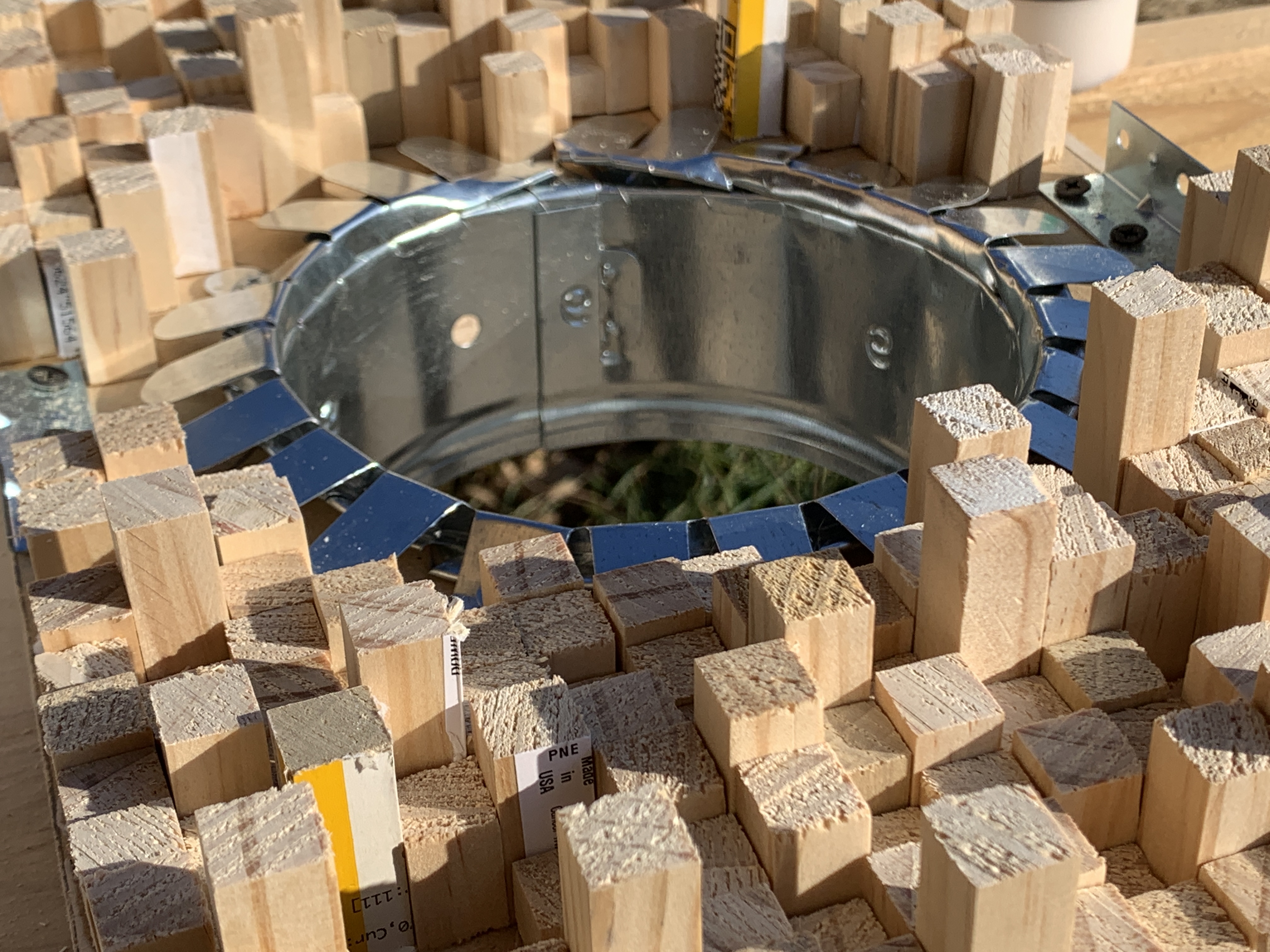
I used 6" duct collars for the inlet & outlet. The fans on the ASIC had a 5.5" diameter so maintaining 6" ducting will ensure there is no restriction in air flow through the ASIC.

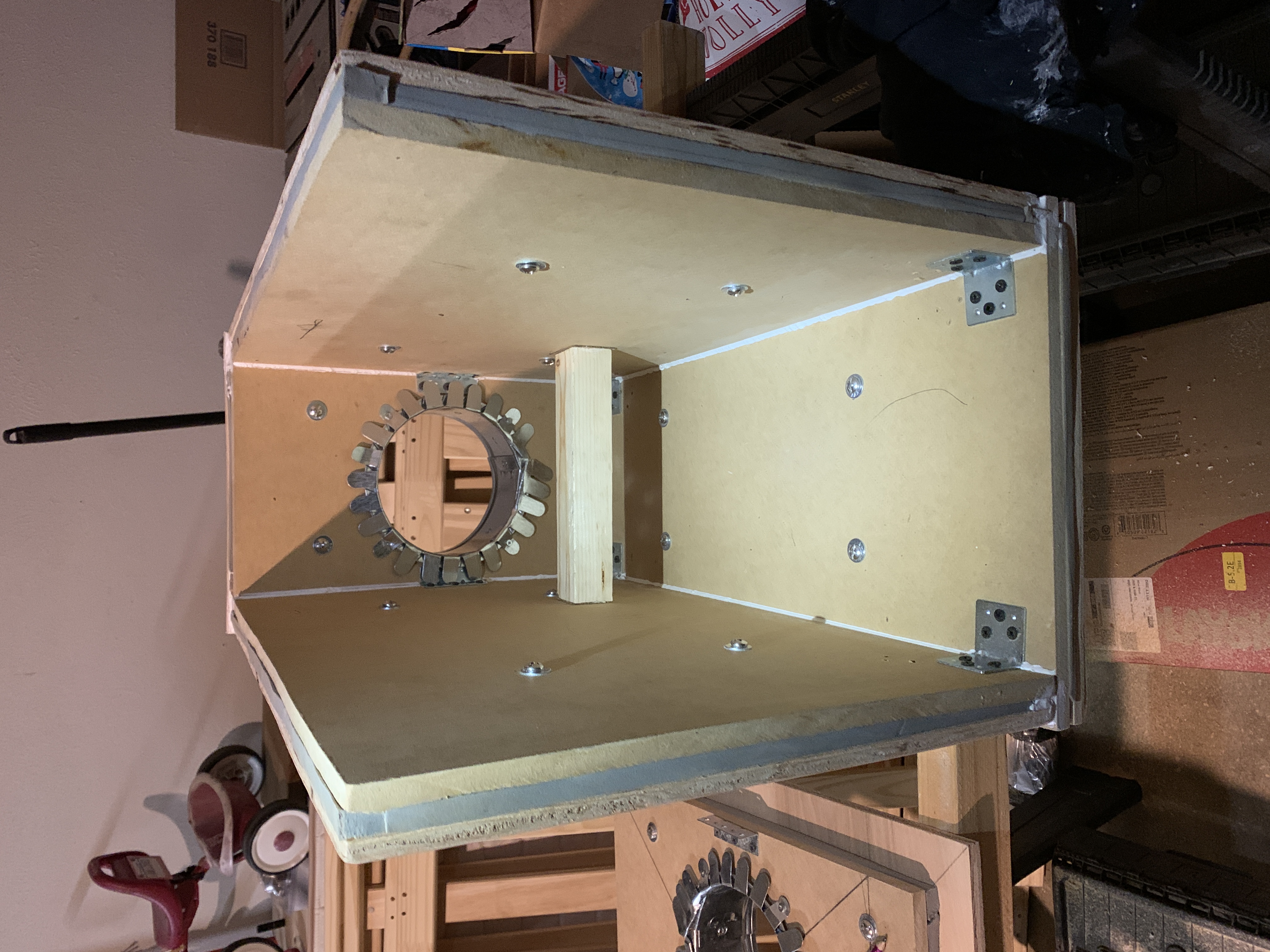
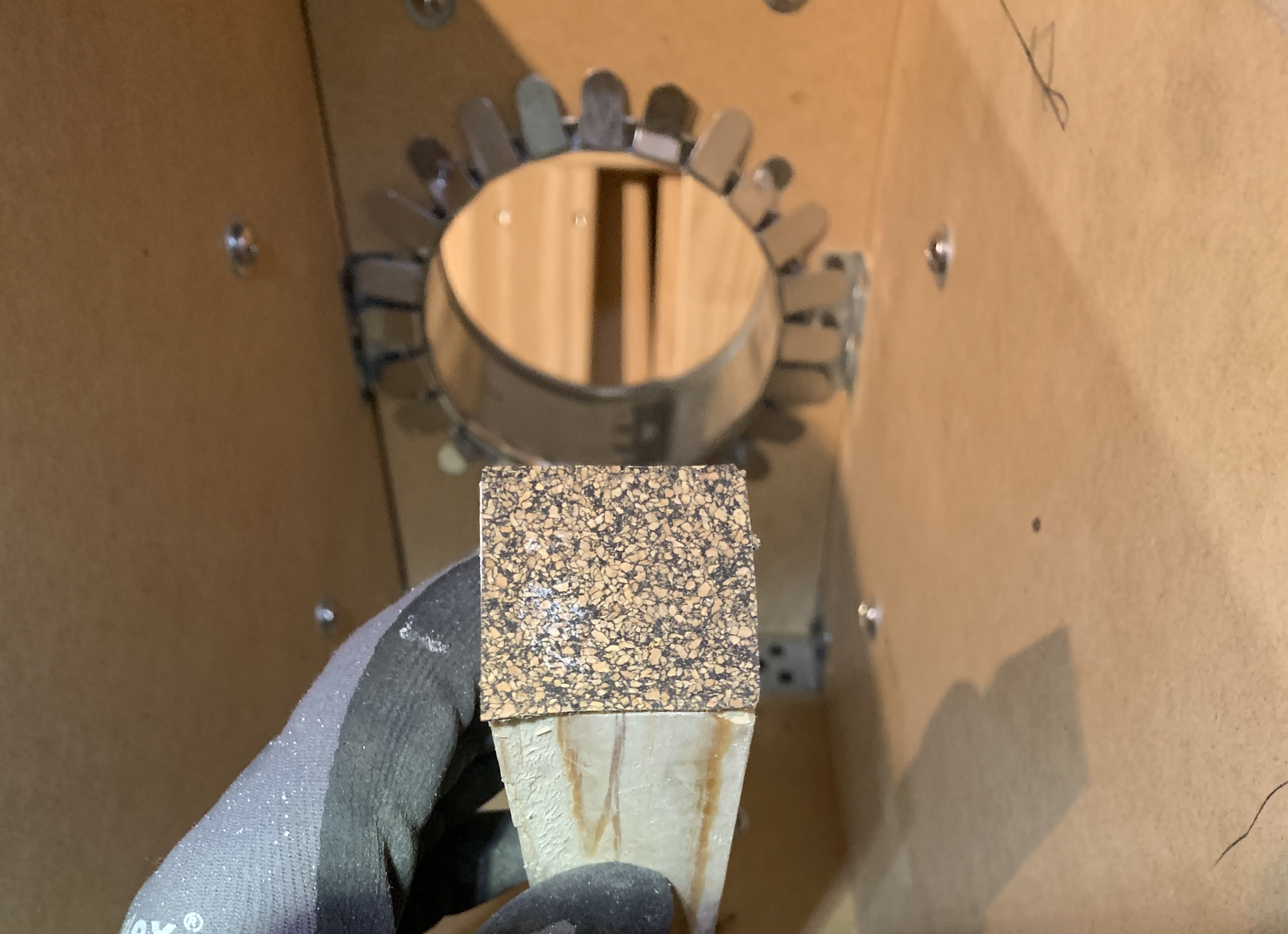
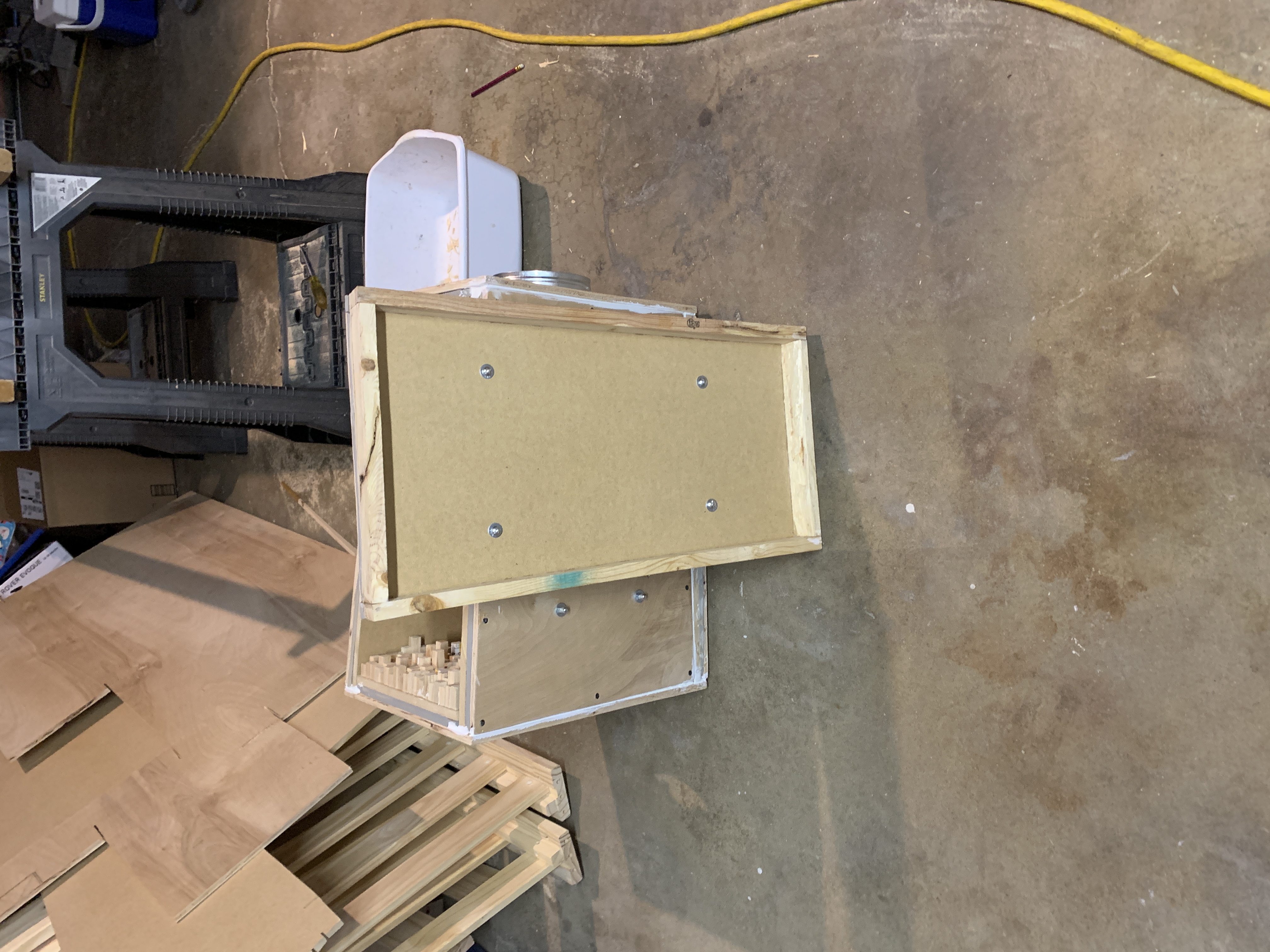
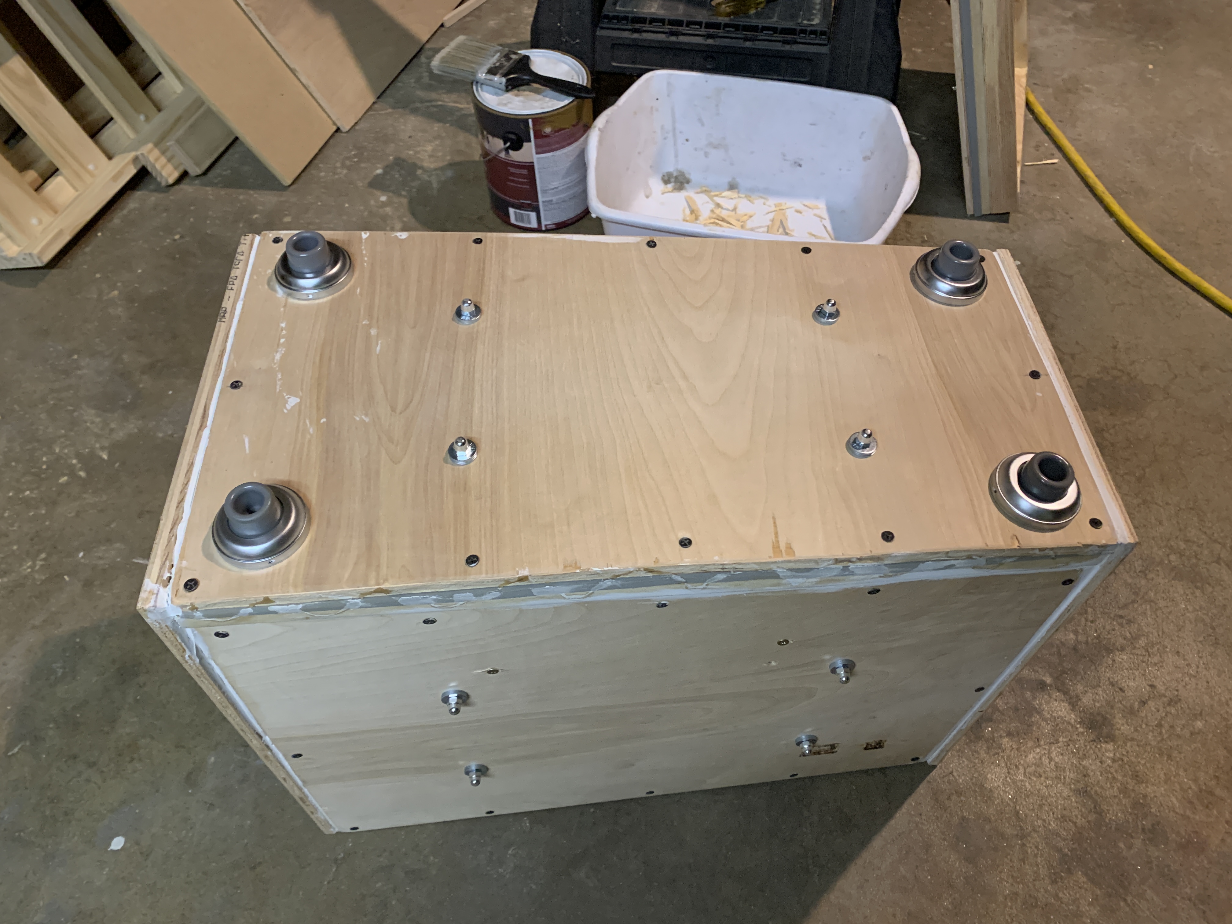
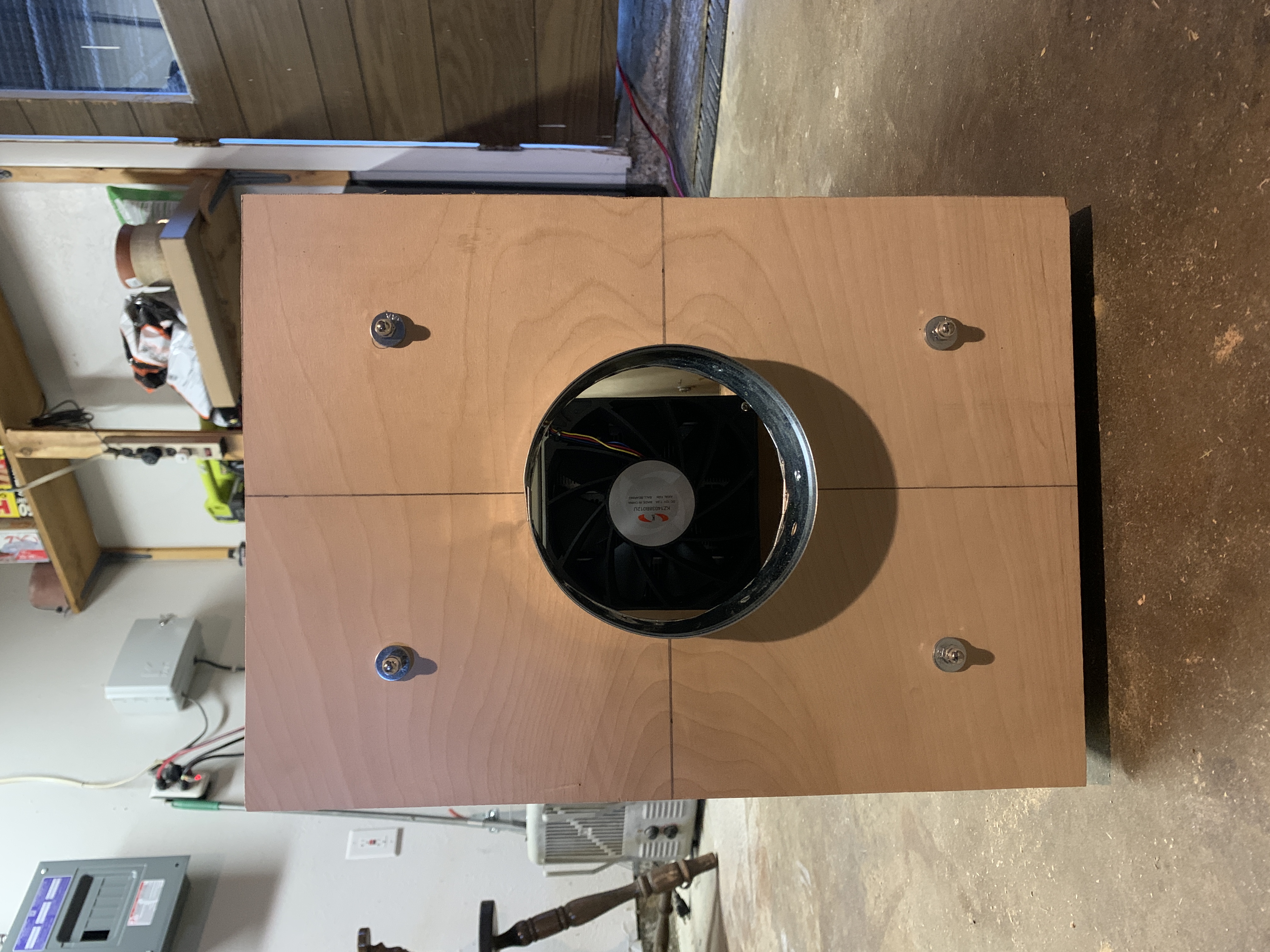
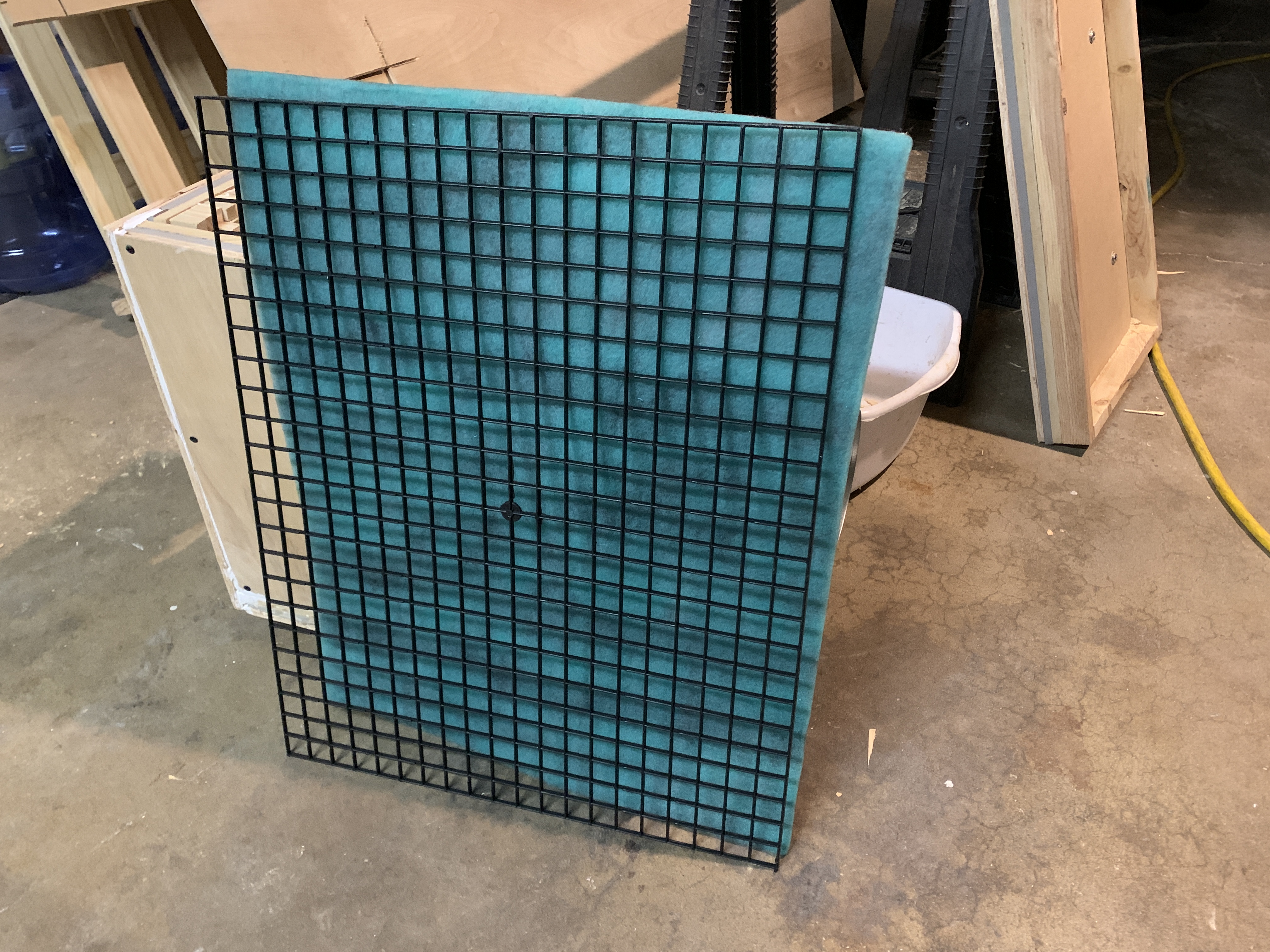
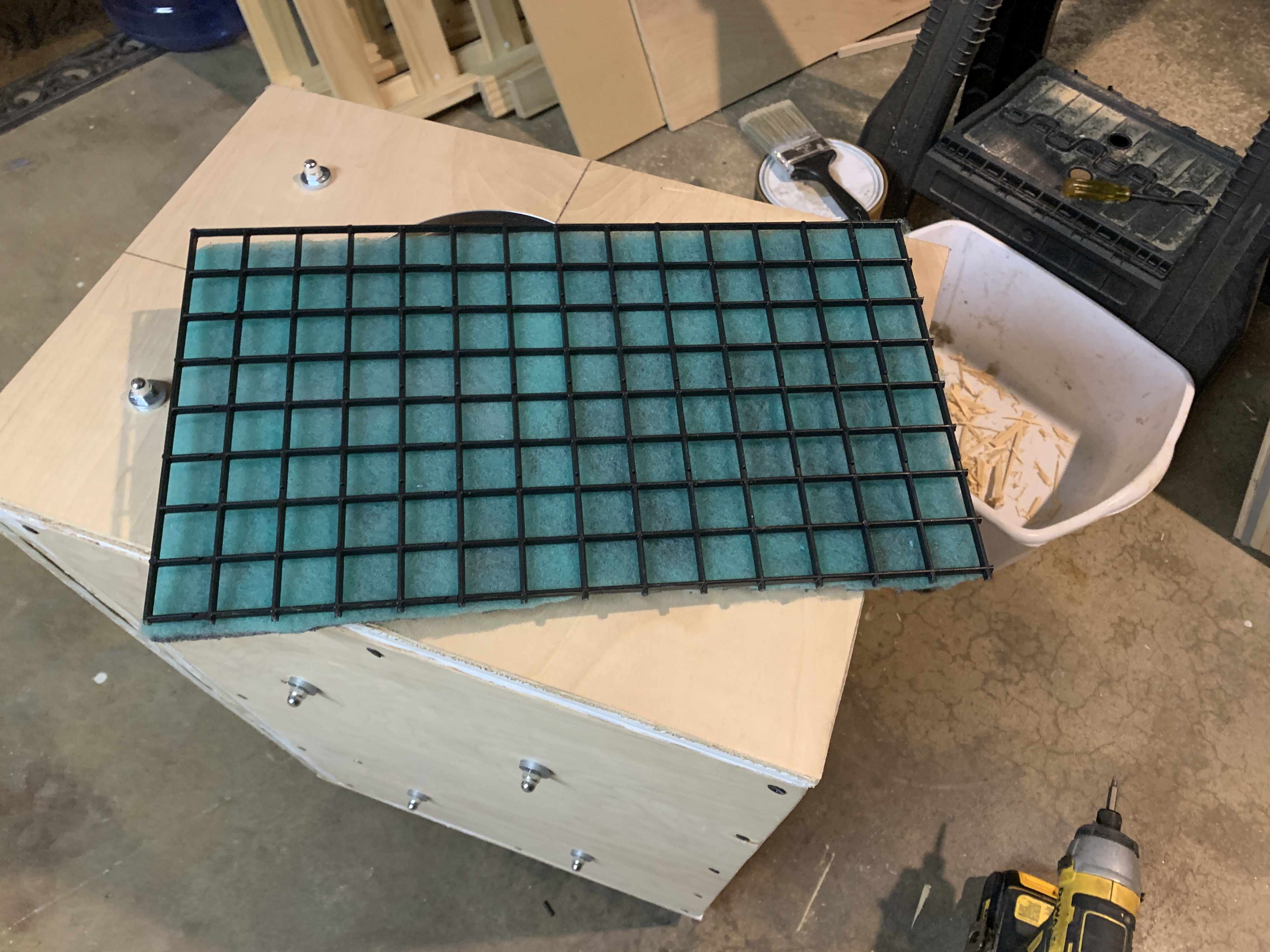
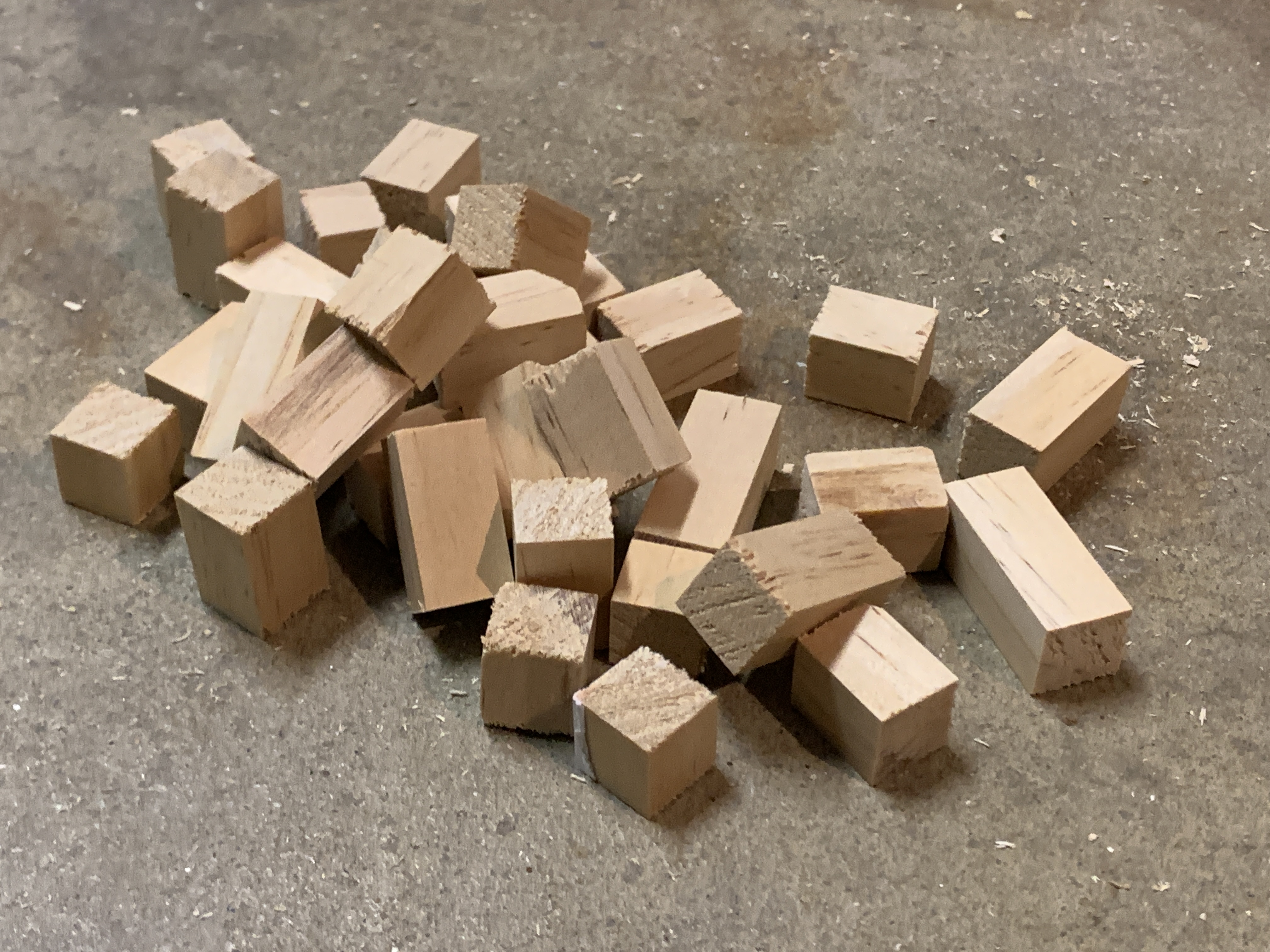
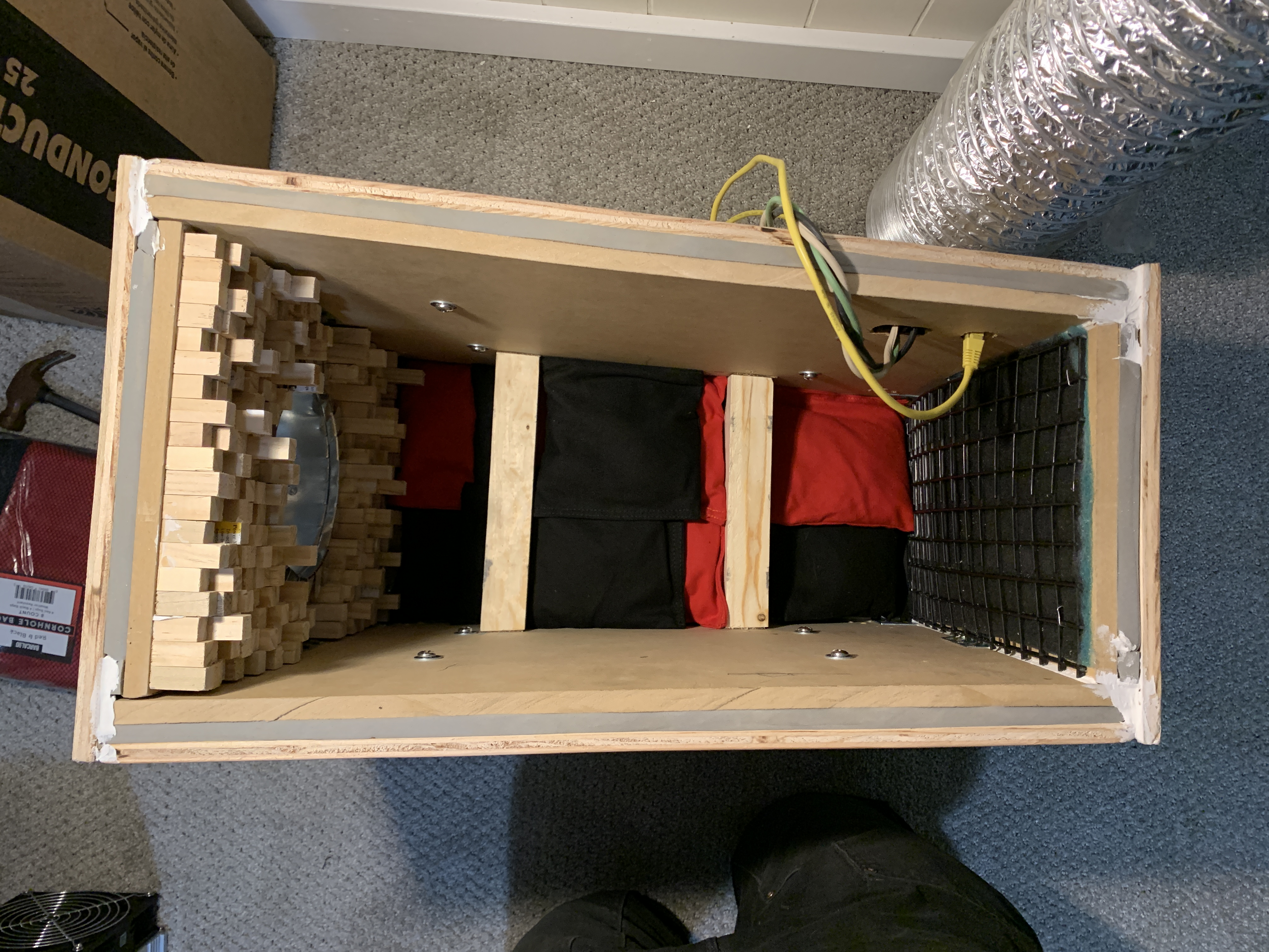
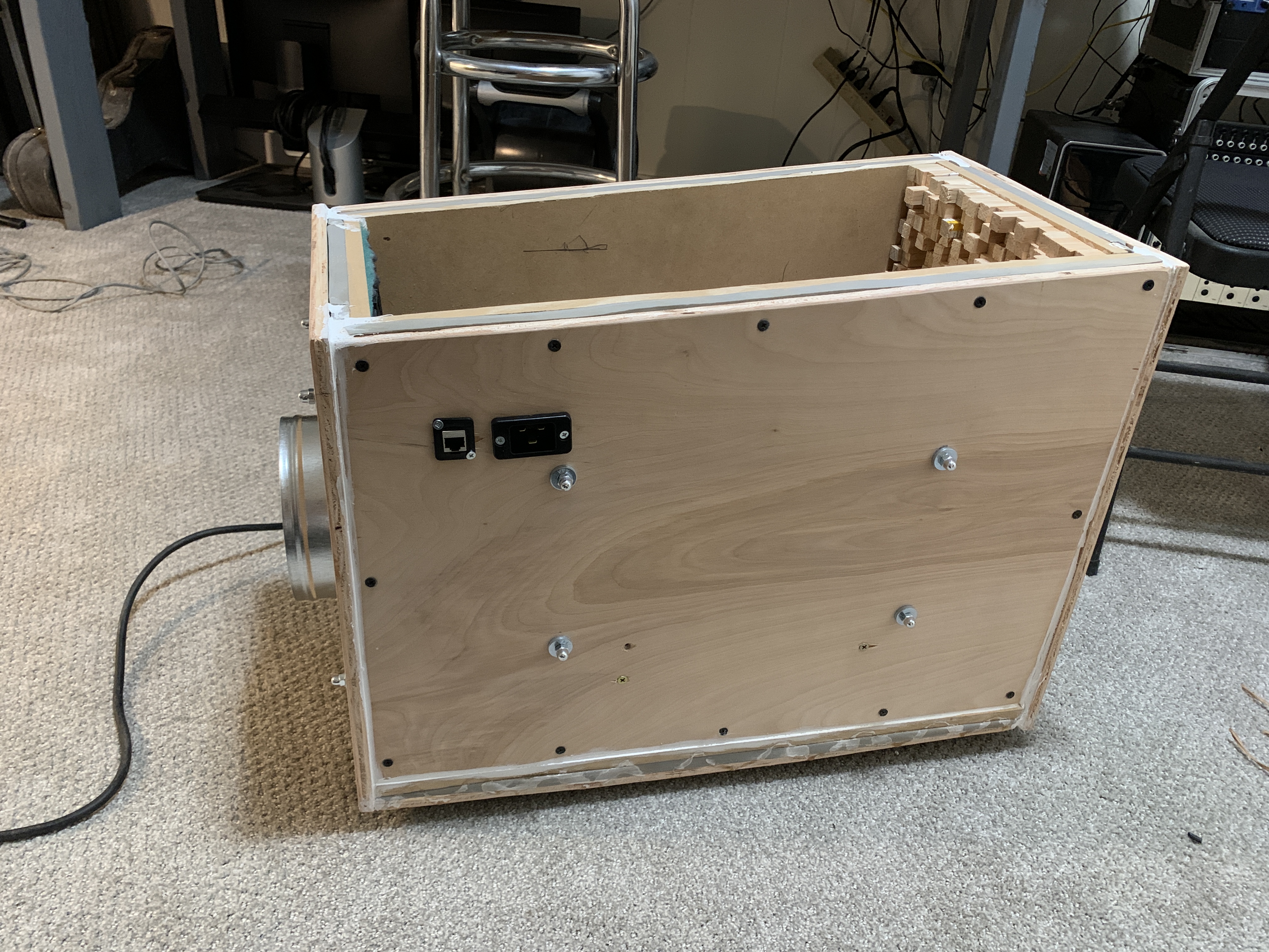
In order to mitigate the amount of dust and debris getting in the circuit boards of the ASIC, I installed a furnace element on the inlet side of the enclosure. On the outlet side of the enclosure I used another tool in noise treatment called a diffuser. Diffusers are purposely made of uneven material so that the sound waves don't have smooth, flat surfaces to reflect off of and bounce around all willy-nilly. I made this diffuser out of 1/2" pine square stock cut to random lengths.
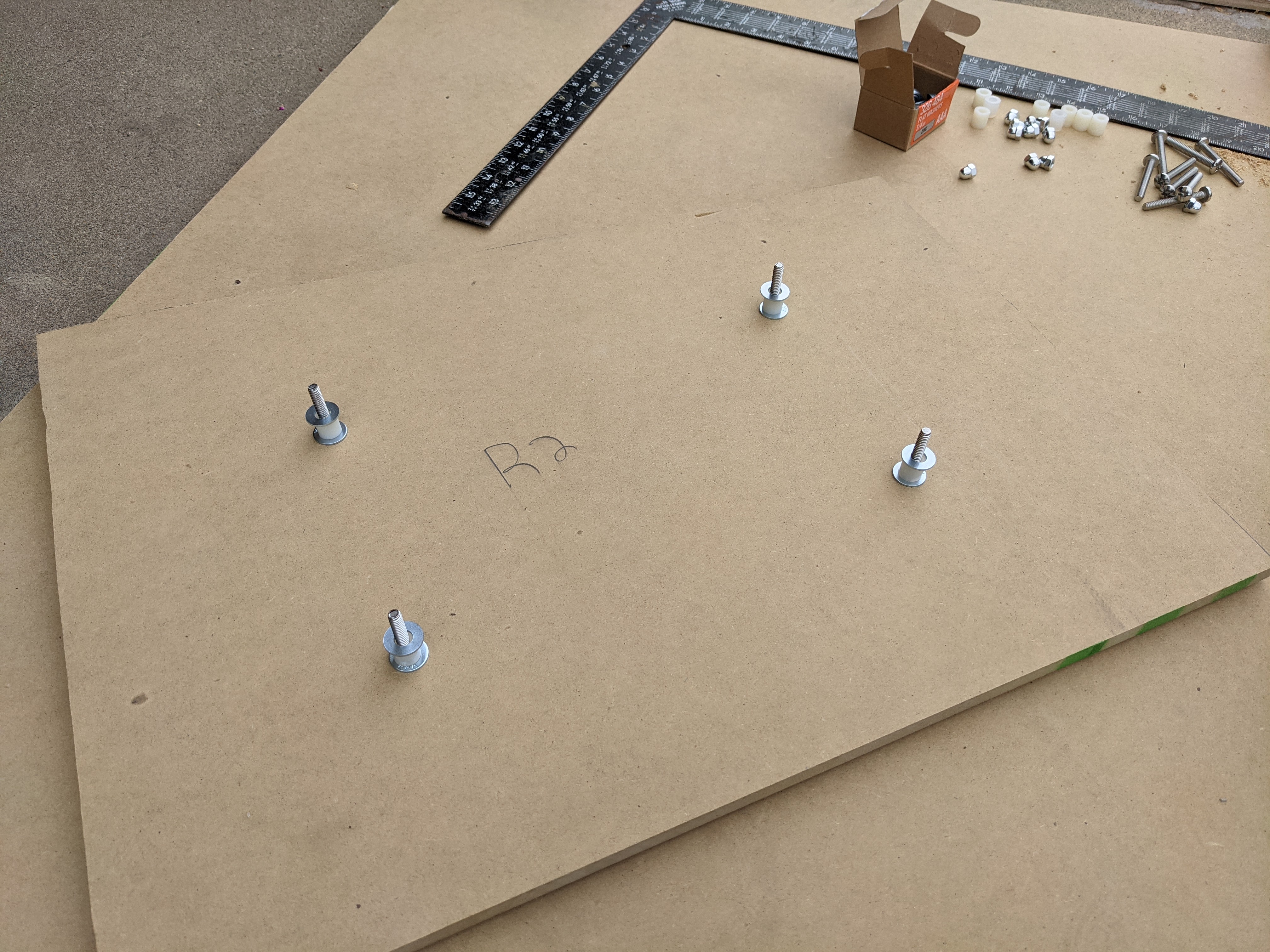
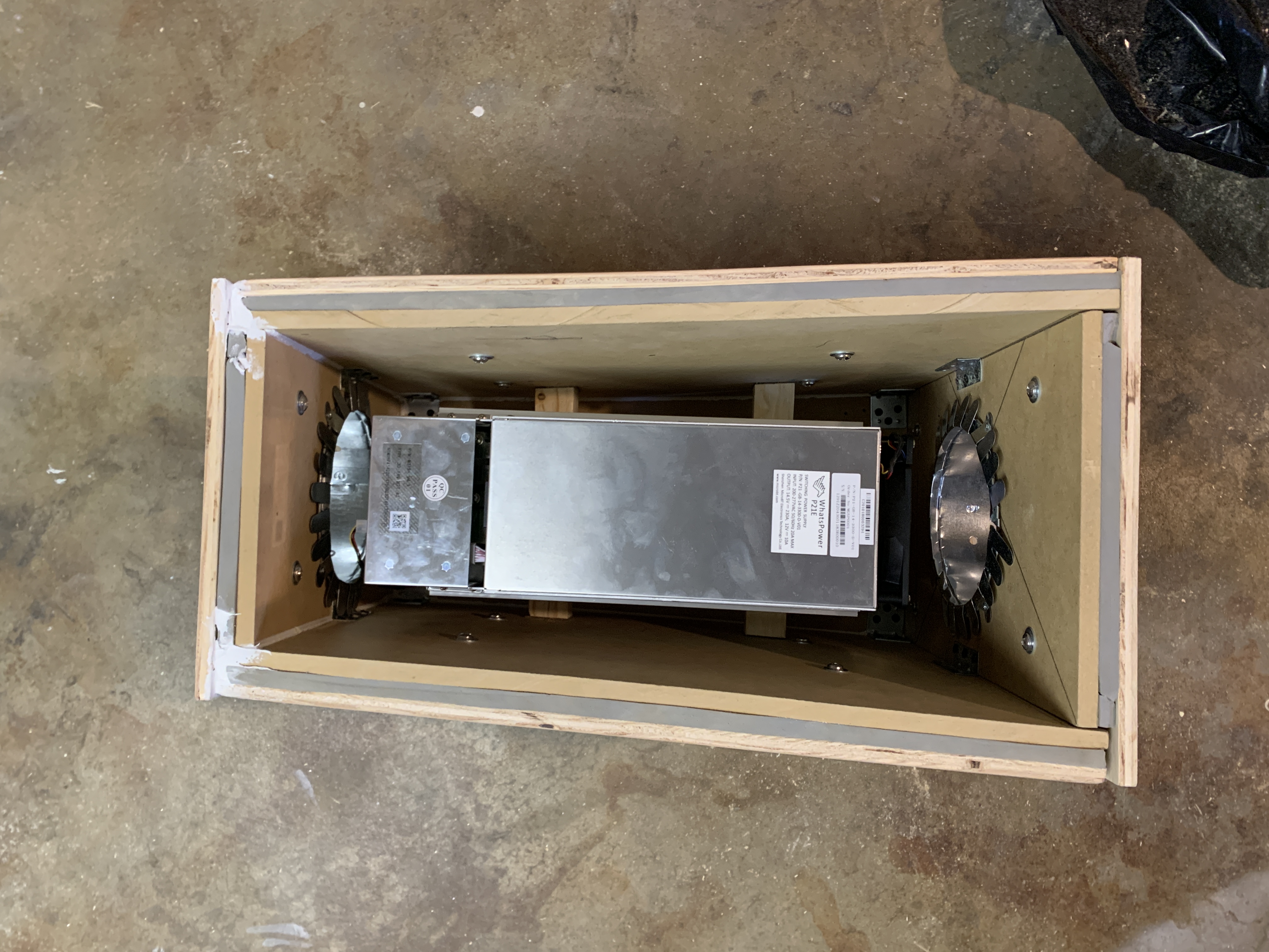
My original idea was to use several small canvas bags filled with sand to pack around the ASIC machine inside of the enclosure. My logic was that this would prevent the air from going around the ASIC tube when it should be forced through the tube and also that the sand bags would add another layer of dense material to help with the noise treatment.
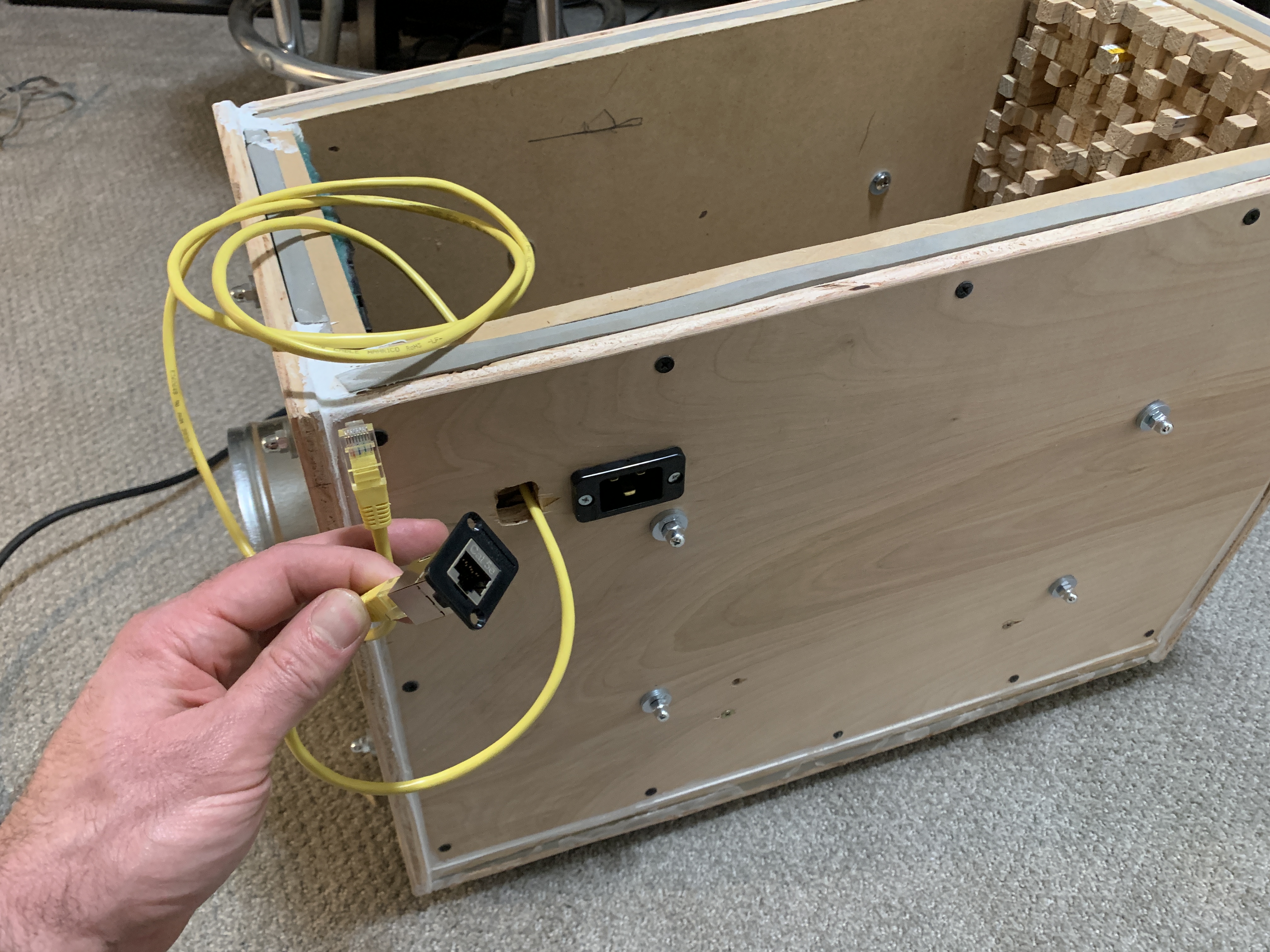
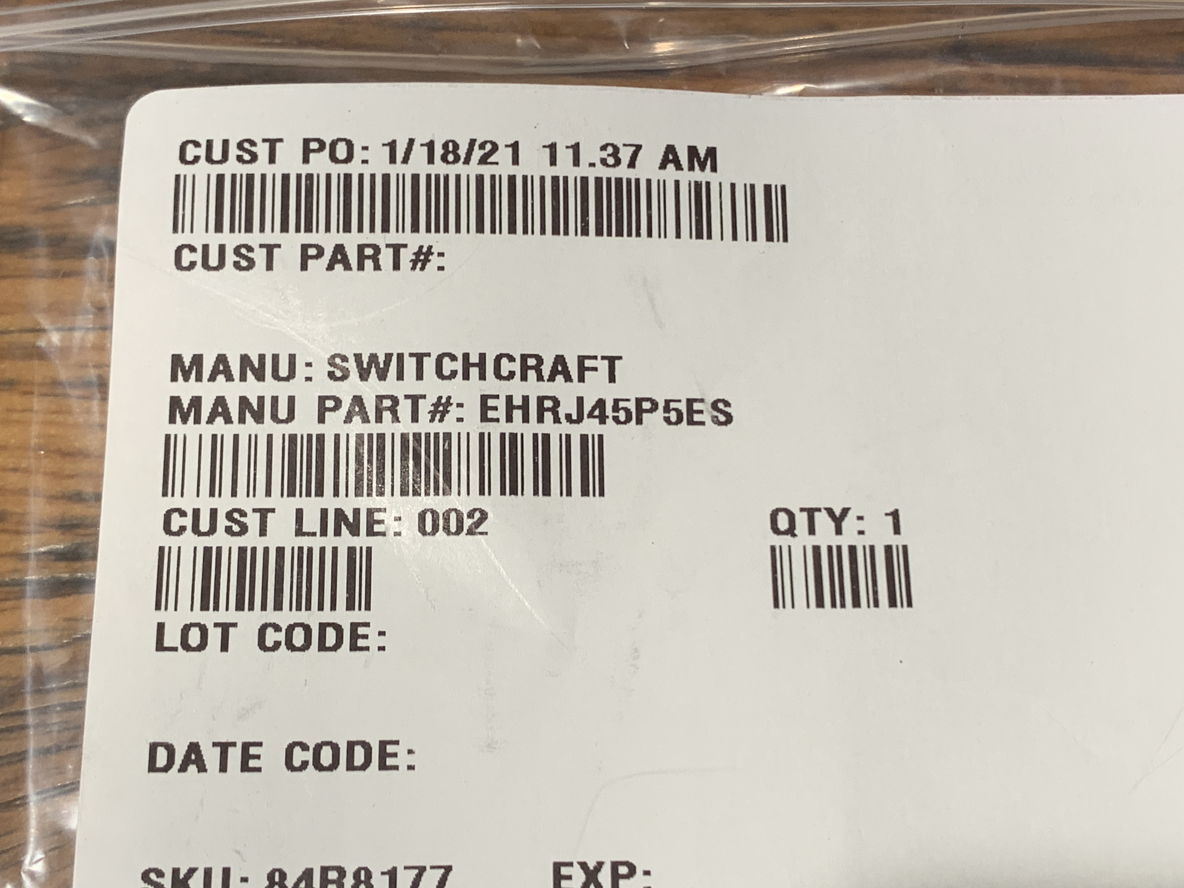
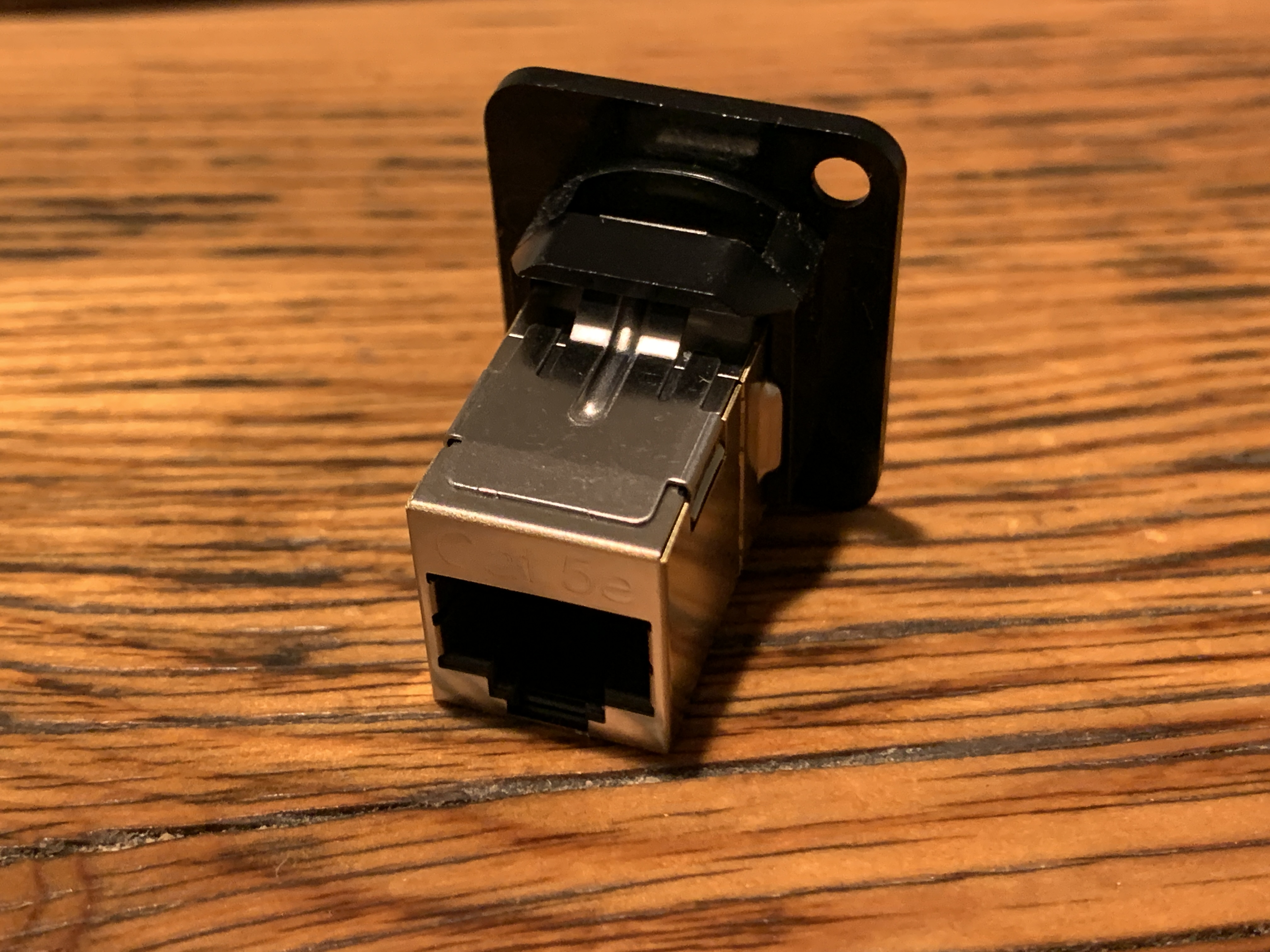
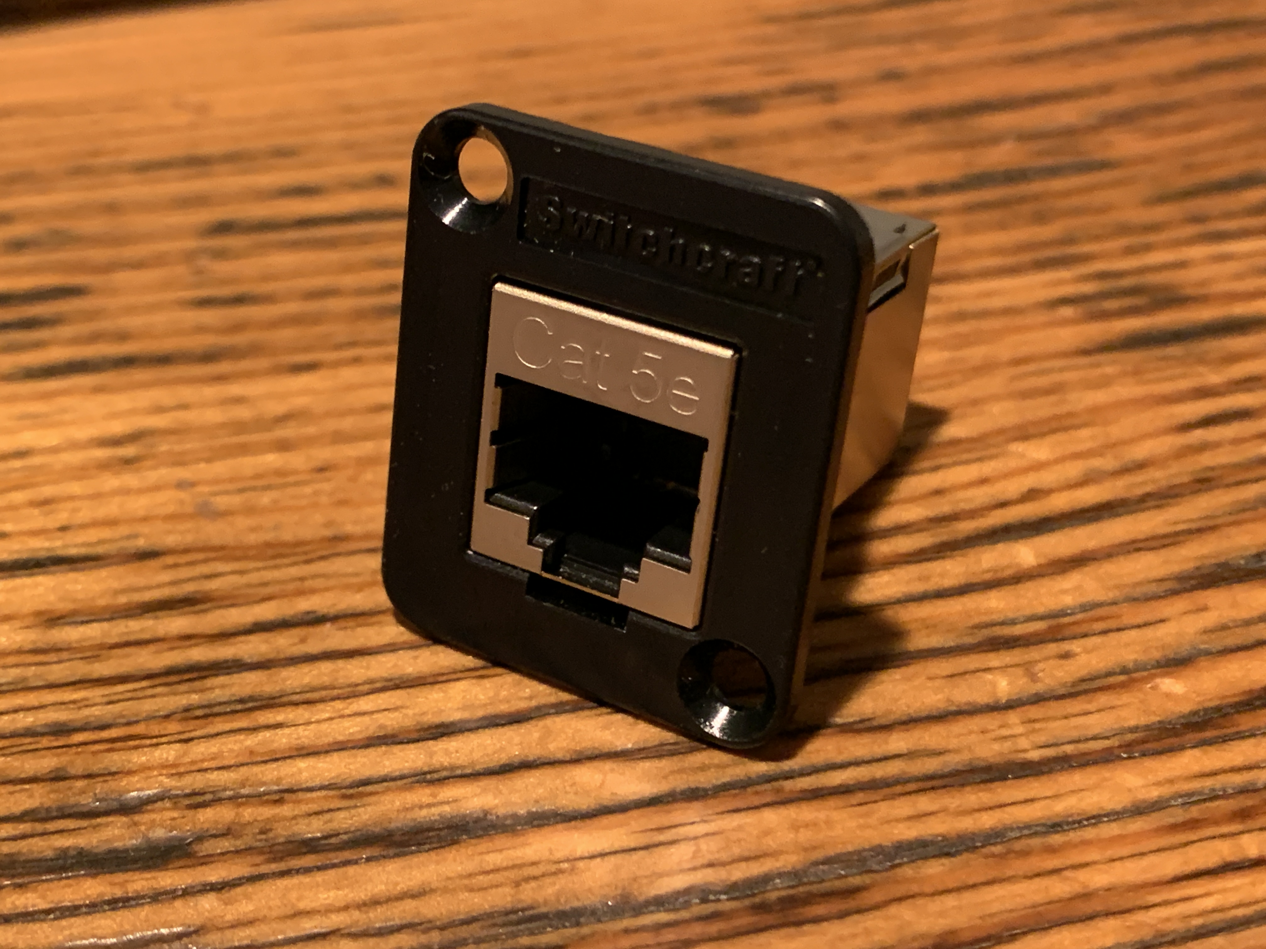
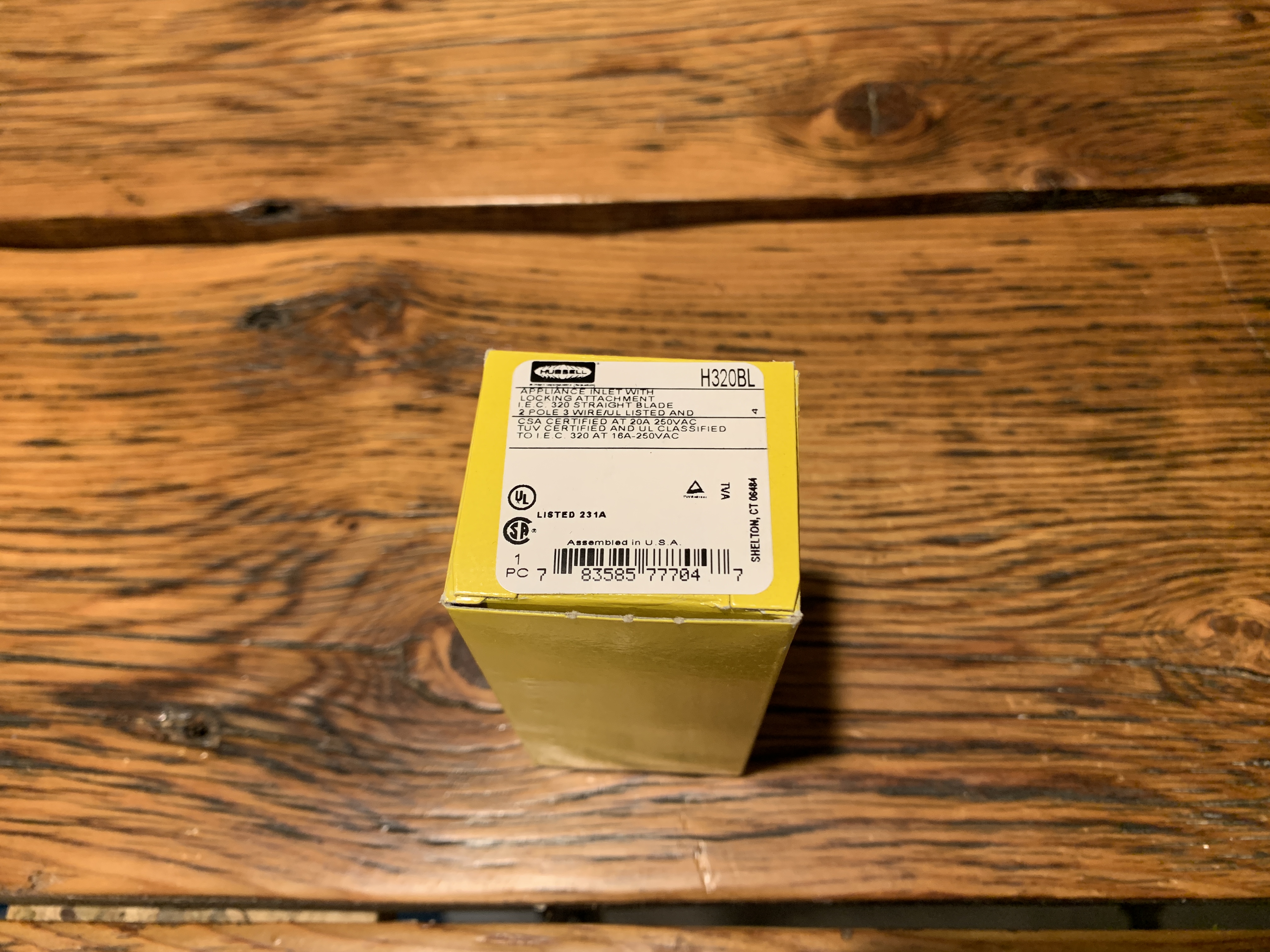
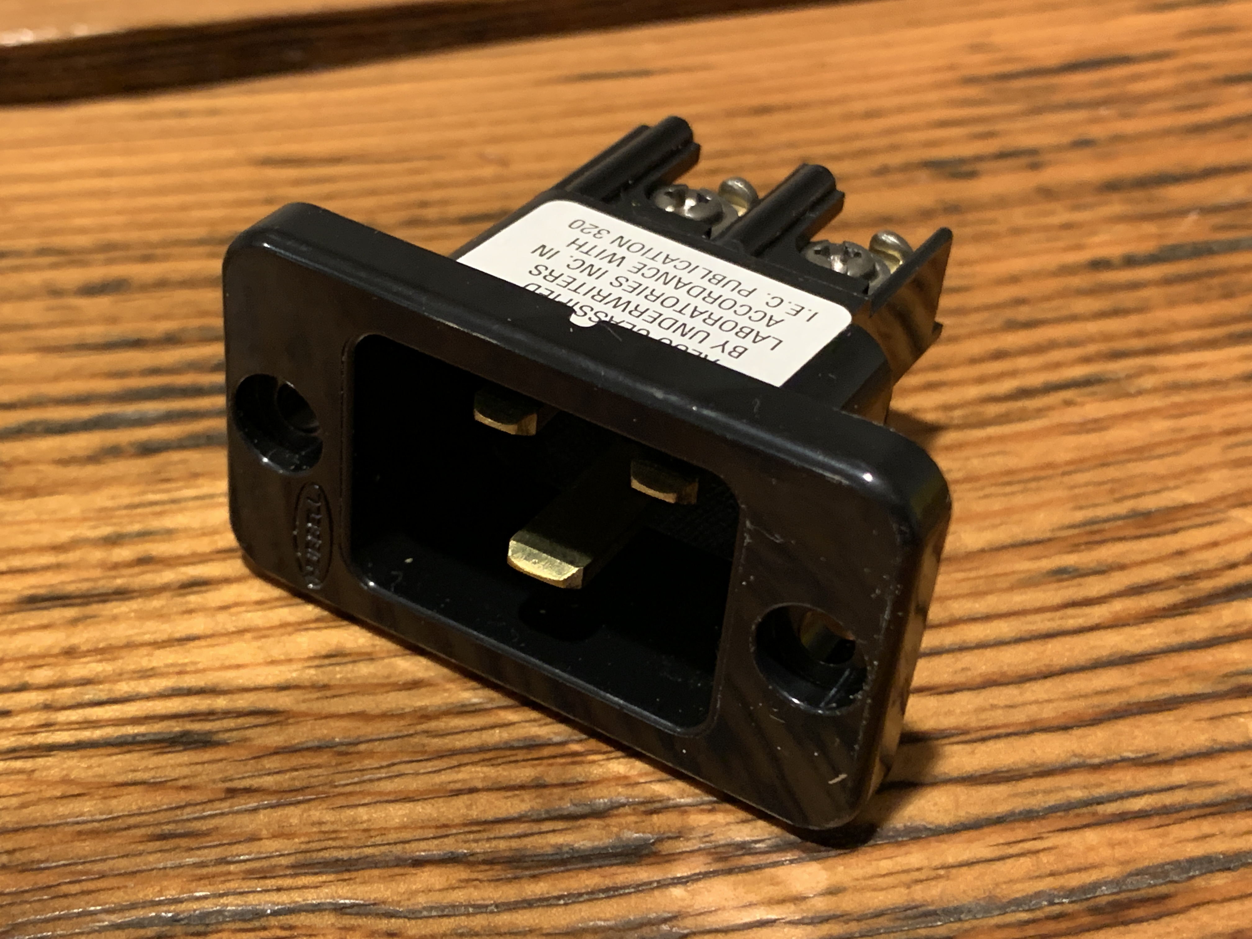
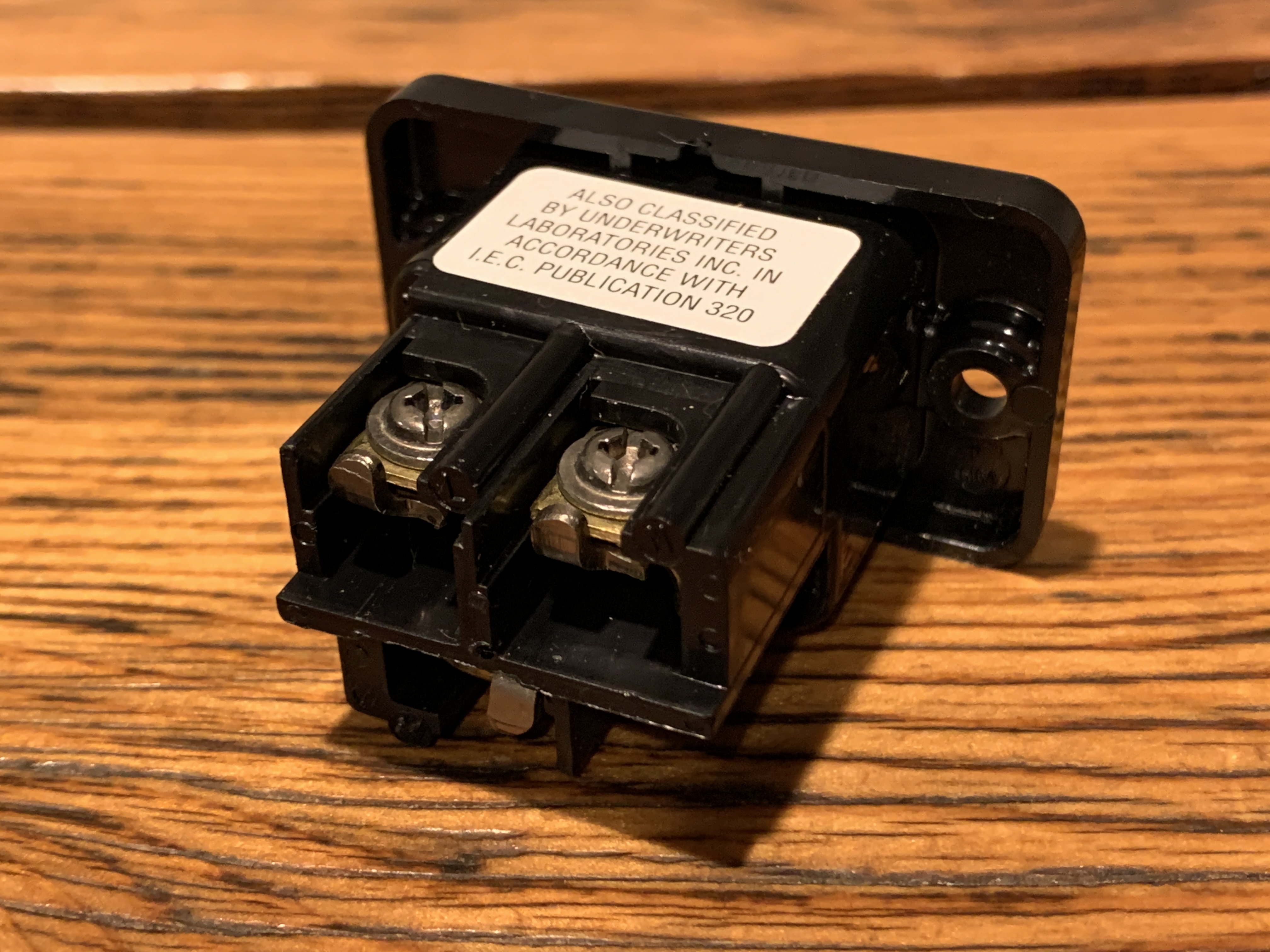
Additionally, I would need to get the power and Ethernet cables to the ASIC somehow. For this, I ordered a panel-mount adaptor for an IEC C19 plug and a panel-mount Ethernet coupling.
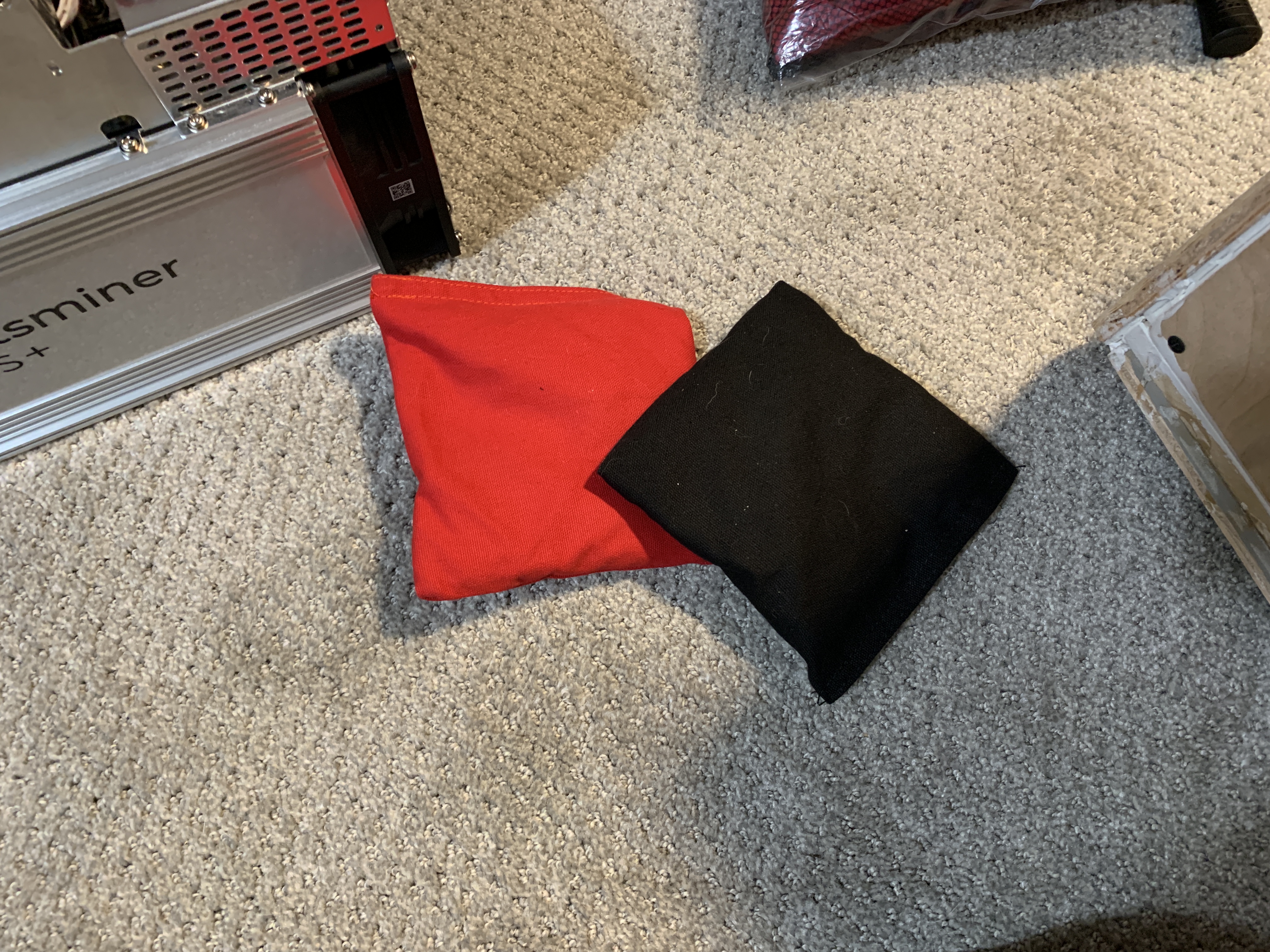
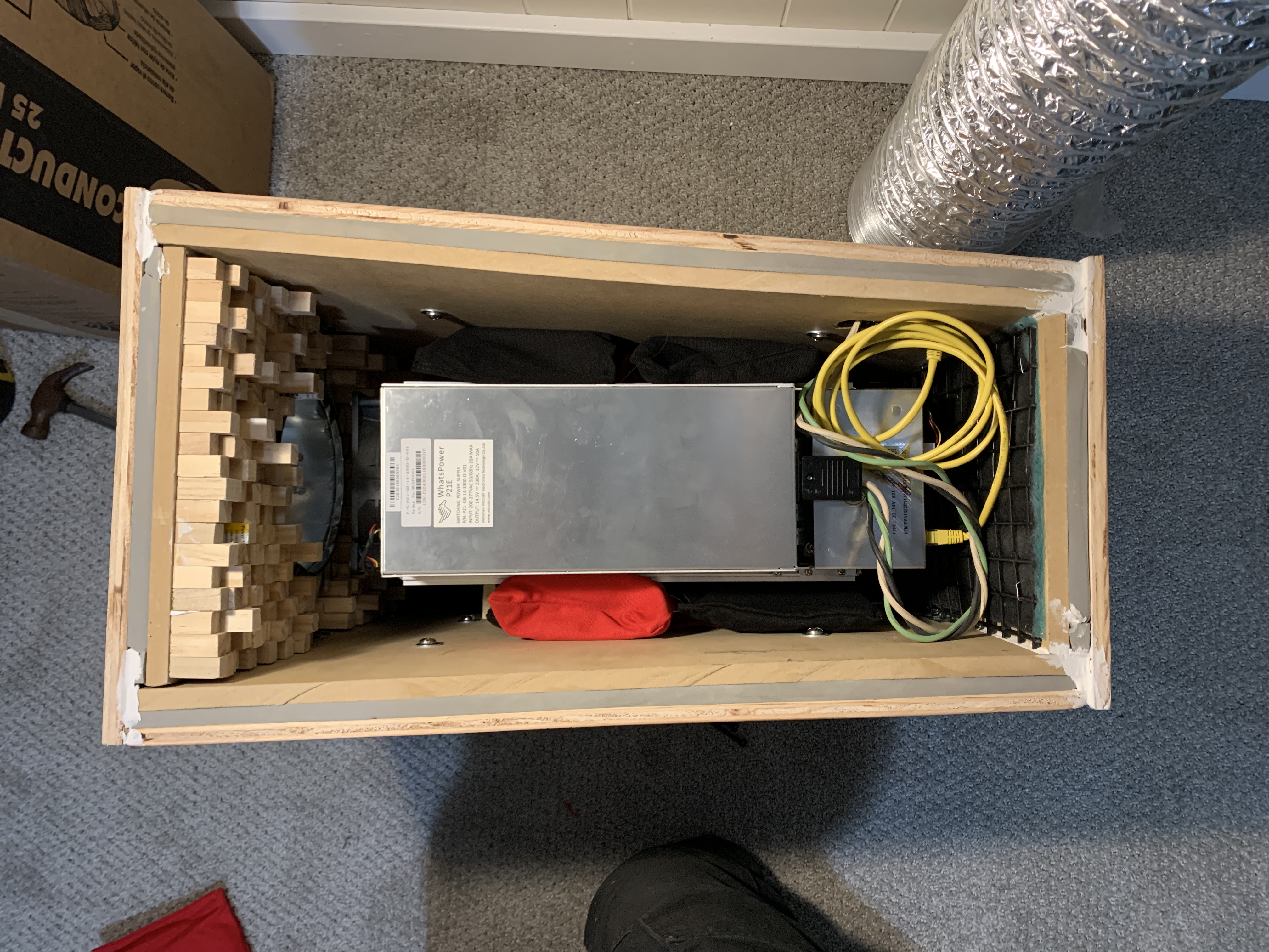
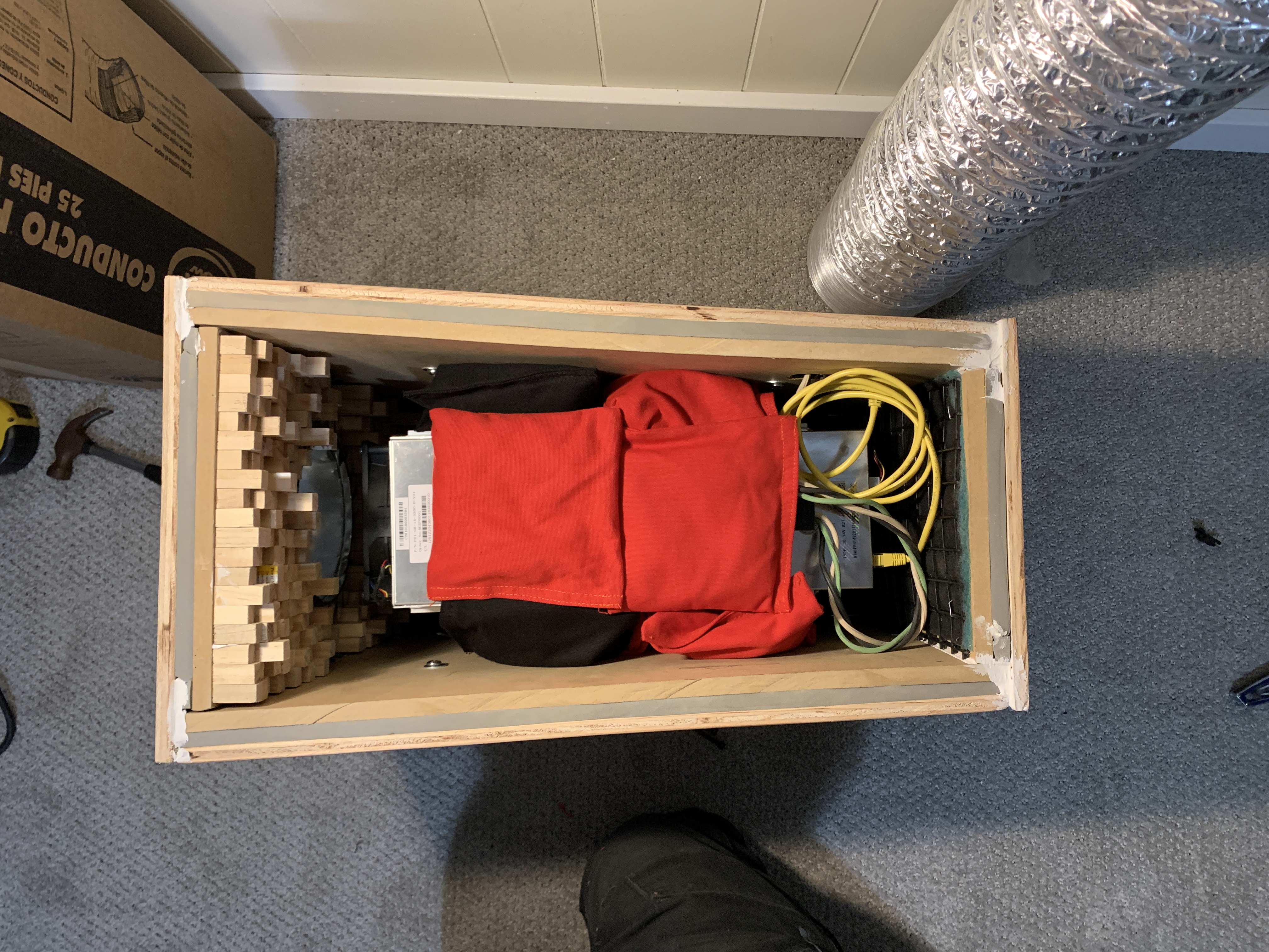
Unfortunately, the sand bags had a negative effect on the ASICS ability to expel heat. The sand bags not only prevented air from cooling the body of the machine but they trapped heat inside the machine. I had to remove the sand bags after the machine reset itself a couple times due to over heating. The sand bags did make a difference on the sound, so I lost a little bit of noise reduction by removing them but over heating the machine was not an option.
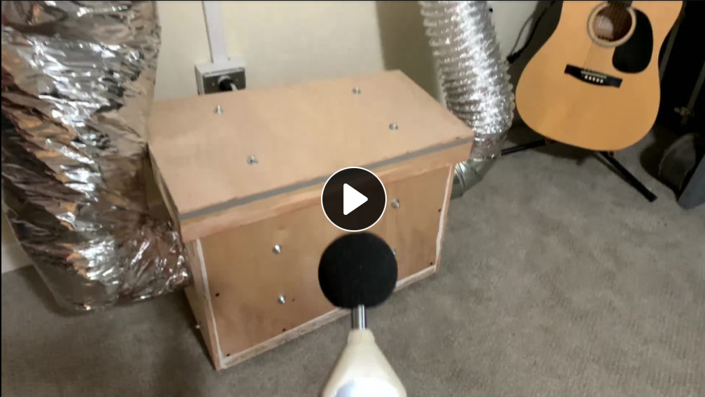
Once finished and installed, my total noise reduction was about 10dB, which isn't as much as I was hoping for but it certainly does make a difference. Technically, a 10dB reduction is perceived by humans as being half as loud as the original un-treated noise, so I'm being hard on myself, it is pretty damn good. I can stand in my kids' room directly above where the machine is installed and I have to really focus to hear the dull hum of the ASIC mining away in the basement. We can sit in the family room downstairs next to the room where the ASIC is installed and enjoy movies or talking without any distraction or interruption from the mining rig. From outside the room that the miner is running, the home's central air system is louder when the furnace is running, completely masking the low mining noise. I am totally content with the noise levels now.
I hope this section revealed to you how loud an ASIC can be and what it means when introducing that kind of power into your living space. I tried to come up with functional and simple solutions to address the noise and I'm happy with the way things turned out. Think outside the box and you can solve any problems that you may encounter while mining at home for non-KYC bitcoin.